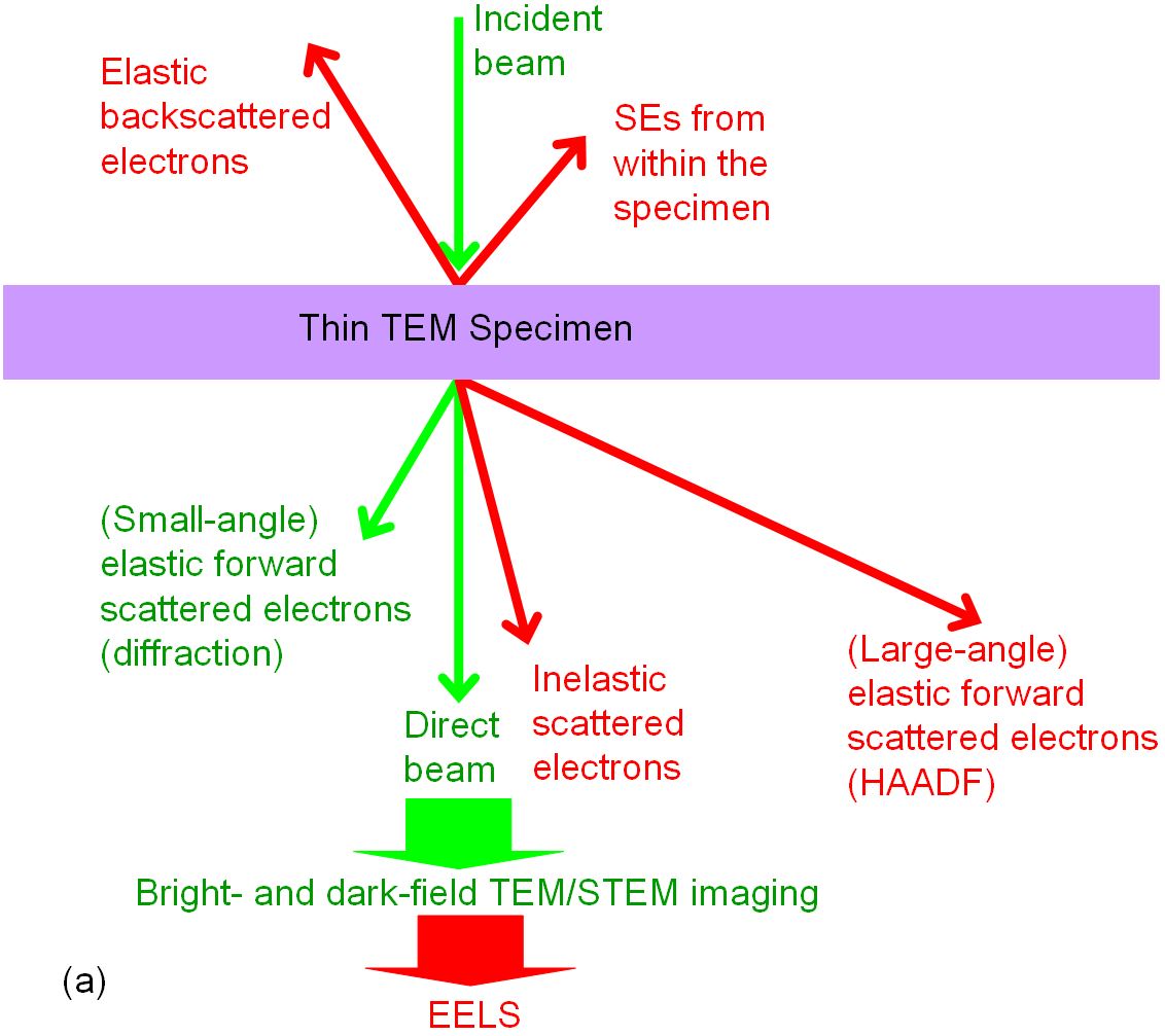
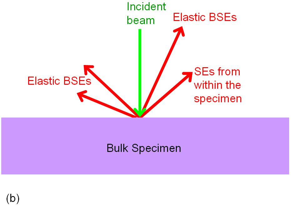
Electron-scattering from specimens in EM measurements can be grouped in different ways. However, the very common and important classification is sorted by elastic and inelastic scattering as listed in Table 1219.
Scattering type |
Energy loss |
Wave (phase) property |
Scattering direction |
Scattering angle |
Electron property |
Full name |
| Elastic |
No energy change of the wave after scattering |
Usually coherent (when the specimen
is thin and crystalline) |
Forward
scattering |
1° ~ 10° |
Wave |
Coherent elastic scattering |
| Incoherent |
> 10° |
Particle |
Incoherent elastic scattering |
| Back scattering |
|
| Inelastic |
There is energy change of the wave after scattering |
Almost always incoherent |
Forward
scattering |
< 1° |
Incoherent inelastic scattering |
| Coherent |
Does not exist in EM measurement, but it shows in neutron scattering |
|
|
Coherent inelastic scattering |
Table 1219b. Coherency of scattered electrons from a specimen in EM (electron microscope) measurements.
Coherency |
Property |
| Coherent |
In phase: preserves the relative phases of the wavelets scattered
from different locations in a material; namely, well-defined
phase relationship between incident and scattered radiation |
| Fixed wavelength |
| The resolution for coherent imaging is much
worse than that for incoherent imaging |
| Useful for diffraction experiments |
| Incoherent |
No phase relationship: does not preserve a phase relationship
between the incident wave and the scattered wavelets |
| Not useful for diffraction experiments |
| The spatial distribution of the scattered
intensity is obtained by summing up the intensities from independent scattering
events |
| Incoherent elastic scattering follows the Rutherford scattering law |
| The resolution for incoherent imaging is much
greater than that for coherent imaging due to squaring an amplitude distribution |
| Incoherent cases: e.g. difference in
wavelength |
| More coherent beam |
Sharper diffraction pattern can be obtained |
Table 1219c. Electron forward- and back-scattering from a specimen in EM (electron microscope) measurements.
Application/effects |
Energy loss |
Specimen |
Coherency |
Full name |
| Diffraction |
Elastic scattering |
Crystals |
Coherent scattering |
Coherent elastic scattering |
| Amorphous solids |
Incoherent scattering |
Incoherent elastic scattering |
| Disordered materials |
| Diffuse background in diffraction pattern |
Mixture of incoherent elastic and
inelastic scattering |
Thick specimen |
Mainly created by incoherent elastic scattering |
| Partially created by incoherent inelastic scattering |
Incoherent inelastic scattering |
| Thermal diffuse scattering |
|
Incoherent |
|
| Compton scattering |
|
Incoherent and inelastic |
|
| HOLZ |
Elastic scattering |
|
Coherent |
Coherent elastic scattering |
| HRTEM |
|
| Weak-beam dark-field images |
|
Contrast after elimination of the incoherent inelastically scattered
background |
|
| Kikuchi lines |
Inelastic + elastic scattering |
Thick specimen |
Two electron scatterings: incoherent scattering (sometimes inelastic) is followed by coherent elastic scattering (Bragg diffraction). |
|
| Practical diffraction pattern |
|
|
An incoherent summation of independent scattering for millions of electrons due to averaging atomic vibrations during acquisition |
|
| Thickness fringes in TEM images |
|
Crystals |
Fringes become less visible for thicker specimens due to effect of absorption or a loss of coherent |
|
| Fresnel fringes |
|
Coherent |
|
| Electron holography |
Elastic scattering |
Coherent beam and scattering are needed |
Coherent elastic scattering |
| Scattering from single atoms |
Any |
Incoherent |
|
| Scattering
from small objectives of ≤1.5 nm in size |
|
Crystals |
Could be coherent |
|
| Spectroscopy, e.g. EELS |
Inelastic scattering |
Any |
Incoherent scattering: occur with a transfer of energy from the wave to the
material |
|
| Plasmon |
Primay means of inelastic scattering |
|
|
| Scattering angle < 3° |
Elastic scattering |
Crystals |
Coherent |
|
| Bright field STEM with overlap of diffracted discs |
|
| Larger scattering angle |
As the scattering angle becomes larger, the coherency degree becomes less |
Incoherent elastic
scattering (Rutherford scattering) |
| > 50 mrad (~3°) for 300 kV |
Any |
Dominated by incoherent thermal diffuse scattering |
| Scattering angle > 5° |
Incoherent and Bragg scattering is
normally negligible |
| High angle Rutherford scattering |
Incoherent |
| HAADF |
| Z-contrast STEM |
| Z-contrast STEM of silicon at θ > 40 mrad* |
| Mass-thickness contrast |
Crystals |
| Secondary electrons |
|
Any |
Incoherent |
|
| Atomic vibration |
|
Create an
incoherent or partially coherent intensity distribution |
|
Fluctuations in lens
currents |
|
|
Causes incoherence |
|
| Energy spread of electrons from the gun |
|
|
|
Fluctuations in the high
voltage |
|
|
|
| Beam
convergence |
|
|
|
| Smaller source size |
|
|
Better coherency |
|
| Spatial coherence |
|
|
Smaller electron sources
give better coherency (at best only ~ 1 nm) |
|
| Spread of focus due to chromatic aberration |
|
|
Causes incoherence |
|
| Field emission guns |
|
|
High degree of coherence |
|
| LaB6 electron guns |
|
|
Low degree of coherence |
|
Table 1219f. Factors which affects coherency in EM (electron microscope) measurements.
Table 1219g. Coherency effects in EM (electron microscope) measurements.
Table 1219h. Types of coherencies in EM (electron microscope) measurements.
Table 1219i. Single and multiple electron scattering.