Wedge FIB Milling Method for TEM Specimen Preparation - Practical Electron Microscopy and Database - - An Online Book - |
|||||||||
| Microanalysis | EM Book https://www.globalsino.com/EM/ | |||||||||
| ================================================================================= | |||||||||
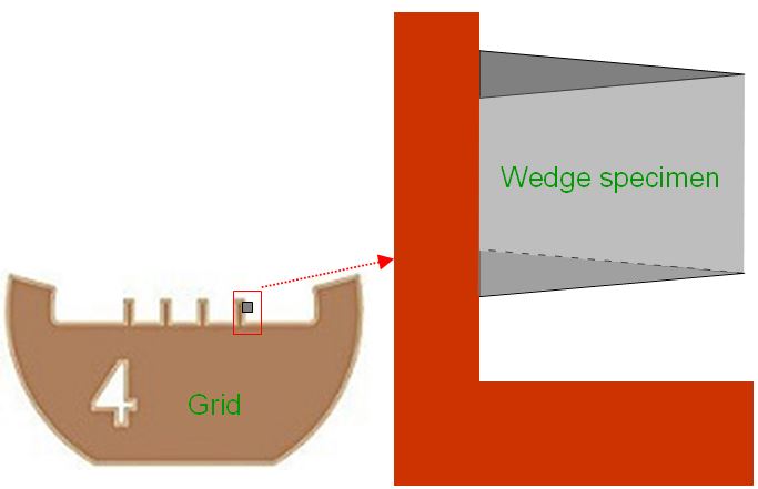
Similar to wedge-mechanical polishing for TEM specimen preparation, wedge method also is widely used in FIB-TEM specimen preparations since it can obtain various specimen thicknesses to satisfy different needs in TEM-related techniques. Figure 1431a shows the schematic illustration of a wedge-shaped TEM specimen prepared by FIB technology and the prepared specimen is under TEM observation.
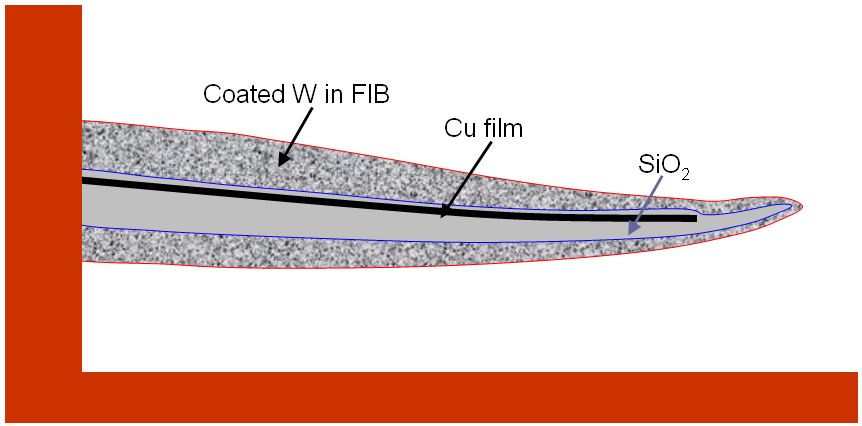
Figure 1431b shows the schematic illustration of a wedge-shaped TEM specimen prepared from a multilayer sample with double-cross-section FIB technique. The copper (Cu) film presents compressive stress in the sandwich sample. Therefore, the TEM specimen bends up because the compressive Cu layer is located in the top portion of the wedge specimen. This type of bending is very common because the different stresses tend to relax in the prepared TEM specimen.
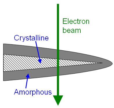
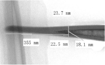
Gao et al. [1] had applied wedge FIB milling method in combination with double cross-section technique to study silicon(Si-) crystal-amorphization induced by FIB milling. Figure 1431c shows a fully amorphized Si portion of 355 nm.
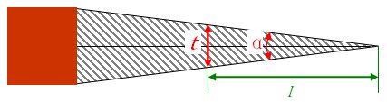
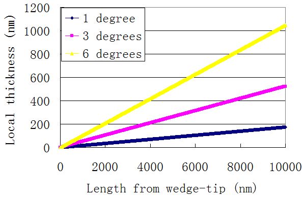
The specimen thickness (t) of the location from the wedge-tip can be given by, t = 2·l·tan(α/2) ----------------------- [1431] Here, t, l and α stand for the dimention and angle in Figure 1431d. Figure 1431e shows the relationship between the specimen thickness and the lenght from the wedge-tip for angles of 1, 3 and 6°. You can also calculate the local thickness for more angles using the excel file.
[1] Qiang Gao, Mark Chang, Chong Niao, Ming Li, W. T. Kary Chien, Experiment Study on Crystal/Amorphous Structure of TEM Sample Prepared by FIB Milling, Proceedings of the 32nd International Symposium for Testing and Failure Analysis, November 12-16, 2006, Renaissance Austin Hotel, Austin, Texas, USA.
|
|||||||||
| ================================================================================= | |||||||||
|
|
|||||||||