=================================================================================
During interaction of incident electrons with the specimen in TEM, one important energy-loss process is atomic ionization, where electrons of atoms are knocked out from the inner (or called core) shells (i.e. K, L, M, etc.) in the specimen. In this case, the shell electrons are moved outside the attractive field of the nucleus, and thus the atom is ionized. This process requires that the inner electron receives an amount of energy equal to or greater than the critical ionization energy, Ec. Therefore, the characteristics originated from the transition of core electrons to unoccupied states in the conduction band require the energy transfer between the incident and core electrons to be greater than its binding energy. The critical ionization energy is a function of the specific atom and the specific electron shell and thus, is uniquely determined. This characteristic signal represents atomic ionization edges in EELS profiles, showing specific energy losses corresponding to Ec and thus presenting the signature of the specific element in the specimen. For a TEM specimen in a proper thickness, the intensity of the 'post-edge' in the EELS profile is directly linked to the concentration of the element. Note that the ionization edges occur at higher energy losses than ~50 eV due to excitation of core electrons into the conduction band.
The excitation of atomic inner shells enables us to study the unoccupied conduction states in a solid. These core-level processes are mostly sensitive to the final states since the initial states have narrow energy widths. Figure 3801 lists the EELS edges which we observe normally. Note that the EELS transitions are named by the initial state.
Figure 3801. EELS edges.
As shown in Figure 3801, the core-loss transitions are conventionally labeled as M23, M45, N23, N45, N67, O23, and O45 and correspond to the transitions from the 3p, 3d, 4p, 4d, 4f, 5p, and 5d states to the excited state levels, respectively. The core loss edges are normally represented by a sudden increase in intensity followed by a decrease in intensity with the increase of energy loss. This sudden rise in intensity in EELS profile represents the ionization threshold, the energy of which is approximately equal to the inner-shell binding energy and thus is characteristic of the element. Note that core-loss edges can be split into two regions, the ELNES, extending 30-50 eV above the edge onset, and the weaker extended electron-energy loss fine structure (EXELFS).
Although the fine structures of core loss spectra give information of the unoccupied density of states, the main application of EELS had still been the elemental quantification until the end of the 1980s mainly because the lack of modeling methods of the ELNES spectra. ELNES analysis has now been commonly applied since theoretical ELNES calculations become easier.
The WIEN2k code has recently been used for the calculation of electron energy loss spectra. [1] Low loss spectra are calculated with the OPTIC package while core loss spectra are calculated with the TELNES program.
Furthermore, the decay of the ionized atom back to its ground state may produce a characteristic X-ray, or an Auger electron. Therefore, these processes of inner-shell ionization loss are different aspects of the same phenomenon.
Plasmon excitation requires much less energy, while ionization requires more energy and thus the ionization cross-sections are relatively small and the mean-free paths relatively large. Therefore, the intensity of ionization in the spectrum is smaller than the plasmon peak and becomes even smaller as the energy loss increases.
The basic core-loss EELS profile and ionization
cross-section is governed by the generalised oscillator
strength (GOS). The GOS represents the probability of a
transition of a bound electron from its initial (ground)
state to a specific state in the continuum.
This transition processes obey the dipole selection rules
Δl = ±1.
The angular (momentum) dependence of the GOS is
Lorentzian in nature and the peak width θE
increases as a function of energy loss.
The core-loss region may be described as follows:
i) A background falling rapidly with energy.
ii) The background contribution Ib must be subtracted to obtain the core-loss signal Ik,
Ik = It - Ib ------------------------------------------- [3801a]
where,
It -- the total integrated intensity over the core-loss integration range.
iii) A core-loss signal, per unit energy, resulting from
single scattering, can be given by, [2]
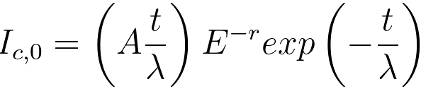 , for E ≥ Ec--------------- [3801b] , for E ≥ Ec--------------- [3801b]
= 0 , for E < Ec--------------- [3801c]
iv) For thin specimens, the electron scattering is single scattering, and then the
observed inner shell edge intensity I(E, β) is related to
the energy-differential cross-section by, [4]
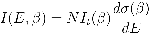 ------------------------------------ [3801d] ------------------------------------ [3801d]
where,
N -- the
areal density of atoms contributing to the ionisation
edge,
β -- the collection semi-angle,
E -- the energy loss,
It(β) -- the plamon signal recorded under the same measurement conditions,
σ(β) -- the cross-section of the core loss.
v) A core-loss signal resulting from multiple scattering
by the nth plasmon can be given by, [2]
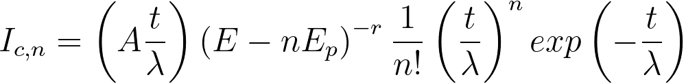 , for E ≥ Ec+ nEp ----------- [3801e] , for E ≥ Ec+ nEp ----------- [3801e]
= 0 , for E <Ec+ nEp --------------- [3801f]
vi) Provided an energy window Δ contains
just N plasmons, then the total core-loss signal resulting from multiple scattering can be given by, [2]
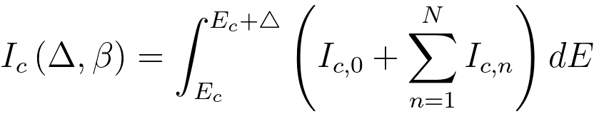 ---------------------------------------------------------------------- [3801g] ---------------------------------------------------------------------- [3801g]
By using Equation 3801g, the number, nc, of atoms associated with the specific
core loss can be evaluated by,
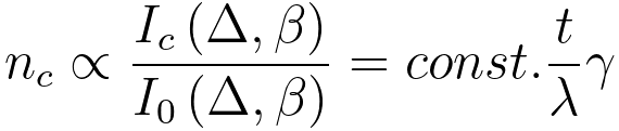 ------------------------------------------------------------------------------- [3801h] ------------------------------------------------------------------------------- [3801h]
where,
γ -- The measure of the departure from linearity in thickness dependence
with results from multiple scattering.
This correction with γ
arises essentially because the multiple scattering produces
extra intensity in the core-loss at energies nEp above the edge. This scattering was assumed to occur with the same cross-section as the average scattering cross-section [3]; however, such approximate treatment will lead to an error because the average energy-loss due to core excitation of the multiply-scattered electrons is actually less than of the singly scattered electrons. [2] γ in Equation 3801h is equal to 1 - ε. Here, ε is zero only when the TEM sample is thin.
[1] C. Hébert, Practical aspects of running the WIEN2k code for electron spectroscopy, Micron 38 (2007) 12–28.
[2] A. P. Stephens, Quantitative microanalysis by electron energy-loss spectroscopy: Two corrections, 5 (1–3) (1980), 343-349.
[3] R.F. Egerton, Ultramicroscopy 3 (1978), 243.
[4] P.J. Thomas and P.A. Midgley, An introduction to energy-filtered transmission electron microscopy, Topics in Catalysis, 21 (4), (2002), 109.
|