Chapter/Index: Introduction | A | B | C | D | E | F | G | H | I | J | K | L | M | N | O | P | Q | R | S | T | U | V | W | X | Y | Z | Appendix
| The schematic illustrations in Figure 4944a show the convergent illumination configurations of various modes in TEMs. In the CTEM condition in Figure 4944a (a), the condenser mini-lens (CM lens) is strongly excited, and incident electrons are focused on the pre-focal point of the objective pre-field, resulting in a parallel illumination on a wide area on the specimen and providing highly coherent electron illumination. In the EDS condition in Figure 4944a (b), the CM lens is turned off and the incident electrons are focused on the specimen by the objective pre-field, resulting in a small-probe illumination. In this case, the illumination angle (α1) is large so that high beam intensity is obtained for a small area in the analytical EDS method. In the NBD mode in Figure 4944a (c), a smaller condenser aperture is used to form a smaller illumination angle (α2). Therefore, a small-diameter probe with relatively high coherence in the illumination is achieved. In the illumination condition in Figure 4944a (c), the illumination angle (α) with a constant probe size can be changed by changing the excitations of the condenser lenses and the CM lens to obtain the incident illumination to form ideal convergent beam electron diffraction (CBED) patterns.
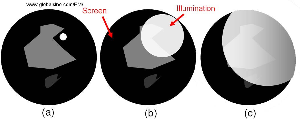
Figure 4944a. Convergent illumination configurations: (a) CTEM mode, (b) EDS mode and (c) NBD mode. In conventional TEM systems, the TEM system is operated at TEM imaging mode and the TEM specimen is illuminated by an almost parallel electron beam. The objective lens is used to form a magnified (intermediate) image of the illuminated area before intermediate and projector lenses. This formed image is further magnified by postspecimen lenses onto the image detector. More readings can be obtained at Difference of Imaging Geometries of TEM and STEM Systems. In TEM operation, the electron beam at near crossover should be centered using the condenser X Y deflection coils (B1 and B2 double deflectors: see page1920) because an unevenly illuminated field of view will be induced when it is opened up if the beam is off center as shown in Figure 4944b.
Figure 4944b. Schematic illustration of uneven illumination if the beam at near crossover is not centered: (a) Beam crossover, (b) Beam is slightly opened, and (c) Beam is ‘widely’ opened. The schematic illustration in Figure 4944c presents the position of illumination part in typical TEM systems.
Note that we need to recalibrate the condenser lens adjustment from the FilterControl software if the EEL specimen illumination changes when the spectrum offset is changed.
|
||||||||||