=================================================================================
The schematic illustrations in Figure 2685a show the convergent illumination configurations of various modes in TEMs. In the CTEM condition in Figure 2685a (a), the condenser mini-lens (CM lens) is strongly excited, and incident electrons are focused on the pre-focal point of the objective pre-field, resulting in a parallel illumination on a wide area on the specimen and providing highly coherent electron illumination. In the EDS condition in Figure 2685a (b), the CM lens is turned off and the incident electrons are focused on the specimen by the objective pre-field, resulting in a small-probe illumination. In this case, the illumination angle (α1) is large so that high beam intensity is obtained for a small area in the analytical EDS method. In the NBD mode in Figure 2685a (c), a smaller condenser aperture is used to form a smaller illumination angle (α2). Therefore, a small-diameter probe with relatively high coherence in the illumination is achieved. In the illumination condition in Figure 2685a (c), the illumination angle (α) with a constant probe size can be changed by changing the excitations of the condenser lenses and the CM lens to obtain the incident illumination to form ideal convergent beam electron diffraction (CBED) patterns.
Figure 2685a. Convergent illumination configurations: (a) CTEM mode, (b) EDS mode and (c) NBD mode.
Figure 2685b shows the comparison of the lens conditions between TEM diffraction and TEM imaging modes. Those two modes are the basic modes in TEM operations. The difference between the two modes may only be the strength of the intermediate lens.
Figure 2685b. Comparison of the lens conditions between TEM diffraction and TEM imaging modes.
Figure 2685c presents more details. Figure 2685c (a) shows the principle of magnifying an image (Normal-Mag mode). A transmitted image of the specimen is first formed and magnified by the objective lens, and then is magnified further by two to four lenses, including an objective lens, intermediate lenses, and a projector lens. As shown in Figure 2685c (b), at extremely low magnification (e.g. used for survey of interest), the image is formed by the OM (objective-mini) lens, intermediate lenses, and projector lens. The Diff mode in Figure 2685c (c)presents an electron diffraction pattern. In the Normal-Mag mode, the focus of the 1st intermediate lens is adjusted to the image plane of the objective lens where a selected area aperture is located. However, in the Diff mode, the focus of the 1st intermediate lens is adjusted at the back focal plane of the objective lens. Table 2685 lists the status of the lenses and apertures in different operation modes.
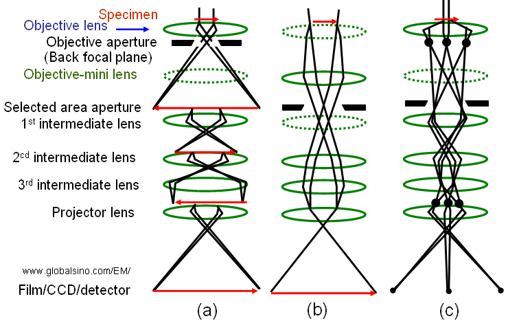
Figure 2685c. (a) Normal-Mag mode, (b) Low-Mag mode, and (c) Diff mode. The dashed-lenses are turned off in the relevant operation mode.
Table 2685. Status of the lenses and apertures in different operation modes*.
Lens |
|
|
|
|
On |
Off |
On |
Objective aperture (back focal plane)
|
Normally use |
Normally not use |
Normally not use |
|
Off |
On |
Off |
|
Normally not use |
Either use or not use |
Either use or not use |
Focus of 1st intermediate lens |
At the image plane of the objective lens |
- |
At the back focal plane of the objective lens |
|
On |
Off |
On |
|
On |
On |
On |
|
On |
On |
On |
|
On |
On |
On |
* "Normal-Mag mode" includes normal and high magnifications for HRTEM; "Low-Mag mode" includes very low magnifications, which is used for specimen survey; and "Diff mode" is for electron diffraction analysis. |
|