=================================================================================
The incident electron beam can be considered as made of a set of incident rays within an incident cone. In two-beam condition, the resulting pattern located in the back focal plane consists of two disks but not of two spots, namely the transmitted and hkl diffracted disks as shown in Figure 3888a (a). Given the strength of the objective lens is unchanged, when the defocus is changed from zero to Δh by adjusting the height of the TEM sample, the transmitted and diffracted beams in the diffraction pattern in the back focal plane will be changed from Figure 3888a (a) to (b). The origin is that the angles (2θB) between the incident and diffracted beam are the same for the two cases but the difference between the distances from the TEM specimen to objective lens results in the difference between r1 and r2. Here, θB is Bragg angle.
In this case, the diffraction spots in the image plane also move. Assuming the strengths of the other lenses in the TEM system are not changed, the diffraction pattern on the TEM screen or detector will be very different from the cases in Figure 3888a (a) to (b). If you are working on TEM-imaging mode, the TEM image will also be very different. The sample height in Figure 3888a (a) is called Eucentric height. Therefore, in order to obtain the Eucentric height in TEM, the incident electron beam should be converged first and then, the defocus distance (Δh) should be adjusted to zero by adjusting the “Z” heights on TEM panel.
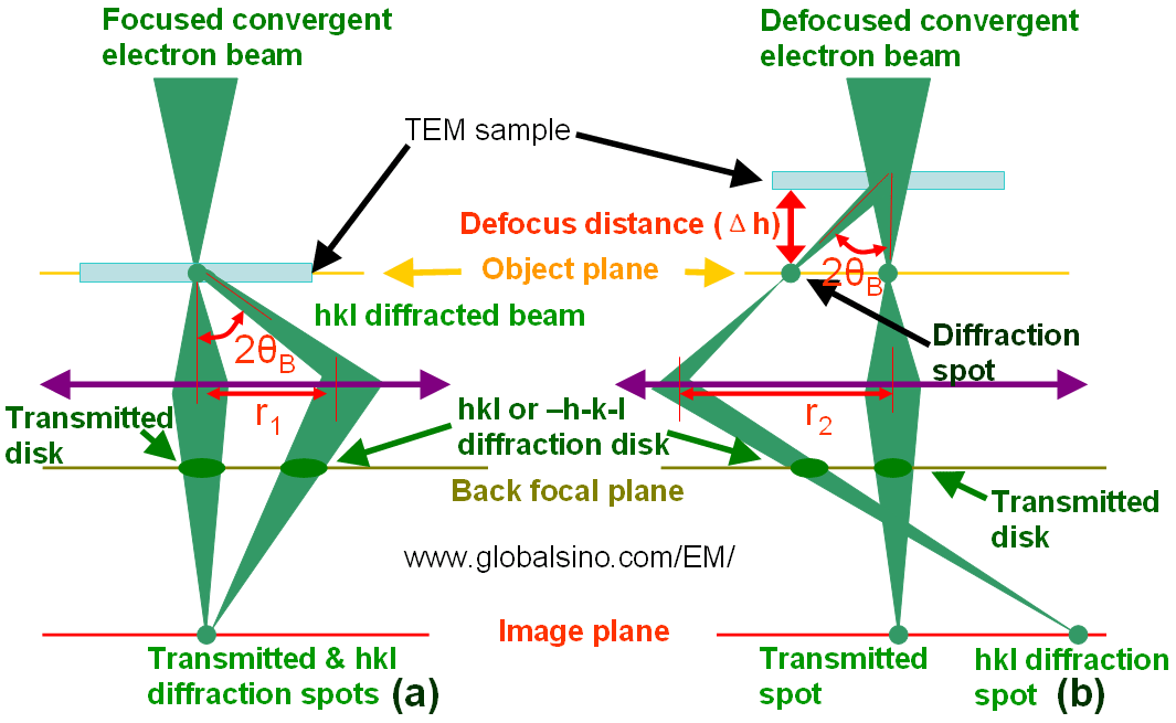
Figure 3888a. TEM optics under conditions of focused (a) and defocused (b) convergent incident electron beams.
If the specimen is at a different height, for instance, it is not at Eucentric height, the beam-illuminating location is not affected by beam shift as shown in Figure 3888b (b), but it is clearly affected by beam tilt as shown in Figure 3888b (a). In order to eliminate this effect in the tilting case, we have to re-adjust the strength ratios of the two deflectors B1 and B2.
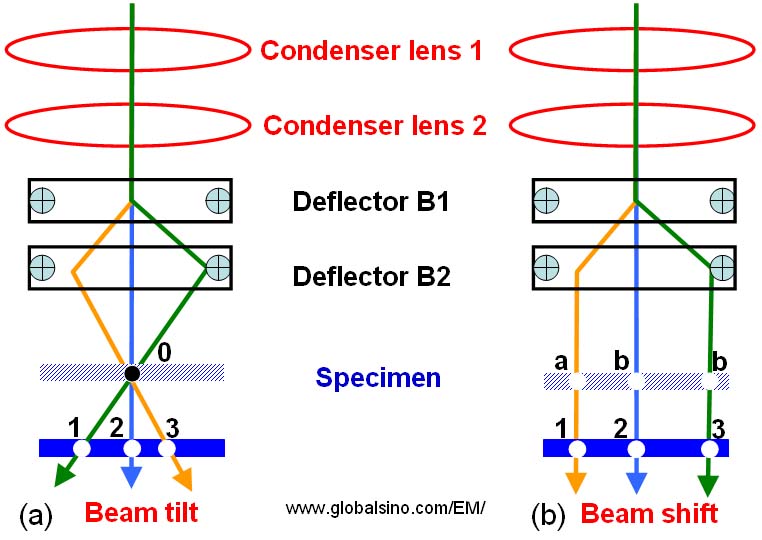
Figure 3888b. Schematic illustration showing the difference of specimen traverses in both beam tilt and beam shift process.
At Eucentric height, the position of the specimen in TEM is at the geometric center of the pole piece of the objective lens.
In TEM image mode, two main ways can be used to obtain a caustic curve:
i) Lower the sample height to below its optimal focus height (standard z-height) when a fine electron probe is focused onto the sample, keeping the objective lens current fixed. At a specific magnification, the size of caustic curve is determined by the height change.
ii) Defocus the objective lens when keeping the sample height fixed. At a specific magnification, the size of caustic curve is determined by the defocus value.
Furthermore, the dimension measurements, e.g. evaluations of critical dimension (CD) and d spacings, in TEM cannot be accurate (normally 10% ~ 100% inaccuracy) if the camera length is in error. To ensure that the installation-calibrated camera length can be used in your experimental measurement, the specimen should be positioned in the "Eucentric plane". This can be done simply by manually tilting the specimen and thus finding the height of the specimen holder where the image of the specimen remains stationary.
On the other hand, the Eucentric position also means that the specimen height is adjusted to be on the tilt axis of the goniometer stage. This can be done, for instance, in FEI TEMs by using the alpha wobbler, L2, to tilt the sample back and forth and adjusting the “Z axis” up or down to minimize image movement.
The phenomena discussed above mostly represent the mechanisms for TEMs with side-entry specimen stages. In this case, using height adjustment for the specimen with goniometer stages, eucentric position can be obtained. Therefore, even if the specimen moves away from the selected area at high tilts, it will not be far from the starting position.
Note that for TEMs with top-entry stages, it is usually noneucentric, i.e. the specimen translates out of the selected area if it is tilted.
The magnification should be calibrated at the film plane. To achieve a magnification and thus dimension measurement exactly as indicated in the instrument, we need to make sure the operation as follows:
i) The specimen should be set exactly at the standard Z-height (namely Eucentric height) in the objective lens. This standard Z-height is defined by the just-focus position and is normally set by the microscope maintenance expert.
ii) The focus of the objective lens should be adjusted to be the just-focus position during each TEM operation.
To have a camera length exactly as labeled in the instrument, some key points need to be satisfied as follows:
i) The specimen should be placed exactly at the Eucentric height in the objective lens.
ii) A parallel electron beam should be employed.
iii) The focus of the objective lens should be exactly adjusted to the focus position.
iv) The focus of the first intermediate (with “Diff focus” knob) should be adjusted at the back focal plane of the objective lens.
|