=================================================================================
In order to improve the energy spread of the electron sources in EMs, monochromators have recently been introduced. In the best cases, the energy spread with a monochromator for any source can be reduced to < ~100 meV. There are two basic setups: the Wien filter with crossed electric and magnetic fields and the electrostatic Omega filter. It is very common that both types improve the energy width to about 0.2 eV at an acceptable beam current of several 100 pA.
On the other hand, lower beam current in the same electron source can be used to reduce the energy spread. Figure 3720 shows the ZLPs (zero-loss peaks) of a CFEG (cold field emission gun) [2] at various emission currents as well as the monochromatized ZLP [3] in logarithmic vertical scale. The inset lists the extraction voltages V1, probe currents Ip and the FWHMs (full width at half maximum) of the ZLPs. Note that the FWHMs quantify the energy spread. In general, the lower extraction voltage and probe current gives smaller FWHMs of the ZLPs, meaning that the higher energy resolution can be obtained, while the one with a monochromator still has the lowest FWHM.
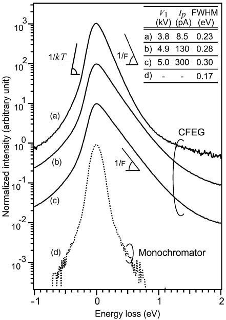
Figure 3720. ZLPs of CFEG under various emission conditions as well as the monochromatized ZLP.
Adapted from [2]
Note that the temporal coherence affects the envelope function because of the energy spread of the electrons, which induces a defocus spread Δ because of the chromatic aberration.
In EMs (especially in TEMs), the temporal coherency effects comes from the small instabilities in the accelerating voltage and electron gun emission over time, which will give the illumination a small energy spread, and from variations in the lens currents, which induces focus variation with time.
Furthermore, the energy spreads in the same microscope can be different at different accelerating voltages. For instance, in a microscope with a Schottky-type field emission gun at energy spread of 0.8 eV (full width at half maximum, FWHM) with an accelerating voltage of 300 kV, the electron monochromator reduced the energy spread to 0.13 and 0.08 eV at 300 and 80 kV, respectively. [1]
The practical (real) energy resolution of EELS in a TEM depends not only on the energy spread of the electron source, but also on instabilities in accelerating voltage of the electron beam, spectrometer energy dispersion and stray electromagnetic field.
Note that occurrence of degradation in the energy spread can be due to the substantial broadening in the detector for EELS if there is cross-talking between neighbouring channels.
For thermal FEGs (field emission guns), electrons are emitted through a reduced potential barrier (reduced by an applied electric field) even when heating the emitter to a lower temperature than the thermal electron emission temperature of 1600 - 1800 K. This phenomenon is also called the Schottky effect. Comparing to cold FEGs, thermal FEGs have disadvantage of large energy spread (0.6 -0.8 eV) because of heating the emitter. However, they have smaller emission noise and produce a stable emission current without gun flashing because there is no adsorption of contamination on the emitters.
With increase of heating temperature in thermionic emission guns, the emission current also increases, the energy spread of emitted electrons becomes wider, and the lifetime of the filament becomes shorter.
Due to the significant energy spread in the electron beam, the chromatic aberration associated with the lenses will lead to image degradation in TEM as listed in Table 3720. On the other hand, as discussed in page4772, the variation of HT and energy spread in the electron sources also induce an increase in probe size in the scanning modes (e.g. SEM and STEM). This effect of the energy spread (ΔE) is proportional to ΔE/E0.
Table 3720. Causes of energy spreads and the image degradation induced by the associated lenses.
[1] C. Kisielowski, B. Freitag, M. Bischoff, H. van Lin, S. Lazar, G. Knippels, P. Tiemeijer,
M. van der Stam, S. von Harrach, M. Stekelenburg, M. Haider, S. Uhlemann, H. Müller,
P. Hartel, B. Kabius, D. Miller, I. Petrov, E.A. Olson, T. Donchev, E.A. Kenik, A.R. Lupini,
J. Bentley, S.J. Pennycook, I.M. Anderson, A.M. Minor, A.K. Schmid, T. Duden,
V. Radmilovic, Q.M. Ramasse, M. Watanabe, R. Erni, E.A. Stach, P. Denes,
and U. Dahmen, Detection of Single Atoms and Buried Defects in Three
Dimensions by Aberration-Corrected Electron Microscope
with 0.5-Å Information Limit, Microsc. Microanal. 14, 469–477, 2008.
[2] Koji Kimoto, Kazuo Ishizuka, Toru Asaka, Takuro Nagai, Yoshio Matsui, 0.23 eV energy resolution obtained using a cold field-emission gun and a streak imaging technique, Micron 36 (2005) 465–469.
[3] Kothleitner, G., Hofer, F., 2003. EELS performance measurements on a new
high energy resolution imaging filter. Micron 34, 211–218.
|