=================================================================================
Figure 3558a schematically shows the relationship between the 7 crystal systems, 14 Bravais Lattices, 32 point groups, and 230 space groups.
Figure 3558a. The relationship between the 7 crystal systems,
14 Bravais Lattices, 32 point groups, and 230 space groups.
Screw axes can be constructed from any proper rotation axis and a translation always along that axis (namely, screw axis = rotation + translation). The degree of the translation is added as a subscript showing how far along the axis the translation is, as a portion of the parallel lattice vector. As shown in Figure 3558b, the symbols for the screw axes are of the form nm: 21, 31, 32, 41, 42, 43, 61, 62, 63, 64, and 65.
Here, the rotation is 360/n degrees, and the translation is m/n units along the screw axis. That is, n is order of rotation, while m/n is the fraction of the unit translation applied in the screw axis operation. For instance, 21 is a 180° (two-fold) rotation followed by a translation of ½ of the lattice vector.
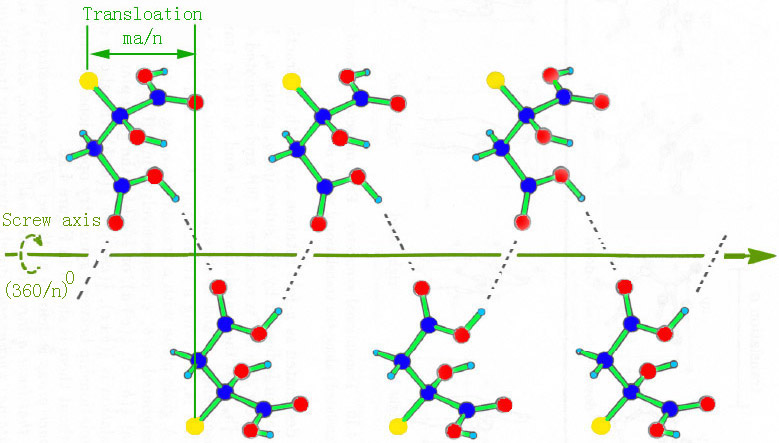
Figure 3558b. nm screw axis. Here, a is the lattice constant.
There are 4 enantiomorphic pairs of screw axes: (31 — 32), (41 — 43), (61 — 65), and (62 — 64), results in 11 pairs of enantiomorphic space groups as listed in Table 3558a.
Table 3558a. 11 pairs of enantiomorphic space groups.
Screw-axes and mirror planes can be deduced from CBED investigation by observing Gjönnes-Moodie (G-M) lines (or called G-M extinctions) and by determining whole-pattern (WP) symmetries, respectively. Gjönnes-Moodie extinction [1] is a type of dynamical extinctions in some electron diffraction patterns. This extinction may occur, for instance, in the presence of a screw-axis or a glide planes because the multiple scattering contributions cancel each other even in the dynamical scattering regime due to destructive interference between contributions with opposite phase.
Table 3558b. Reflections of different screw axes.
| Screw axis |
Reflection condition |
Reflections involved |
Serial extinction law |
Example |
| 21 screw axis (along the a-axis) |
h, k or l = 2n |
|
h 0 0 = 2n + 1 (h = odd) |
|
| 21 screw axis (along the b-axis) |
h, k or l = 2n |
|
0 k 0 = 2n + 1 (k = odd) |
|
| 21 screw axis (along the c-axis) |
|
|
0 0 l = 2n + 1 (l = odd) |
page1669 |
| 42, 63 screw axis |
l = 2n |
h 0 0 for axis || a |
|
|
| 31, 32, 62, 64 screw axis |
l = 3n |
0 k 0 for axis || b |
|
|
| 63 screw axis |
|
000l for axis || c |
000l: l ≠ 2n |
page1878 |
| 41, 43 screw axis (along the c-axis) |
l = 4n |
0 0 l for axis || c |
0 0 l = 4n + 1 (l = multiple of 4: 400, 800,..) |
|
| 61, 65 screw axis |
l = 6n |
|
|
|
| 105 screw axis |
|
|
|
P105/mmc |
For symmetry determination with both XRD and electron diffraction crystallography, we are looking for symmetry-related reflections. Then, the difference between the two techniques is mainly on systematically forbidden reflections:
i) In XRD profiles, the forbidden reflections typically have absolutely zero intensity.
ii) In SAED patterns, such forbidden reflections always have some degree of intensity due to double diffraction from multiple scattering.
Therefore, in SAED analysis, to minimize the multiple scattering, we need to use extremely thin specimens. Fortunately, precession electron diffraction (PED) gives an opportunity to provide closer kinematical conditions than SAED. However, in most cases, the forbidden reflections in PED patterns will not be fully absent since the patterns are produced as a sum of many misaligned electron diffraction patterns and screw axes can only be completely absent if the zone axis of the crystal is perfectly aligned.
For instance, the forbidden reflections in crystals with P21/c (14) space group are caused by 21-screw axis and n-glide plane.
For CBED patterns, a vertical glide plane results in a mirror line. At Bragg condition, a horizontal twofold axis or twofold screw axis in the ZOLZ along g presents a mirror line of symmetry onto disk g, and this line runs normal to g. For a screw axis or glide plane, if the projection of the unit cell in the beam direction has a symmetry, then the forbidden reflections would not be fully forbidden but would obviously be very weak.
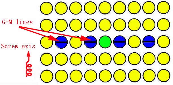
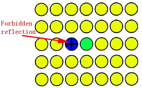
In the CBED patterns in Figure 3558c, the dark bands indicate that the electron beam is either parallel to a glide plane or vertical to a screw axis in the crystal, and the black crosses refer to forbidden reflections.
Figure 3558c. Schematic illustration of G-M lines: (a) A screw axis perpendicular to the electron beam; and (b) Black crosses indicating forbidden reflections. The green disc denotes the transmission beam, the blue discs denote forbidden reflections, and the yellow discs denote the diffraction beams.
[1] Gjönnes, J., Moodie, A.F., 1965. Extinction conditions in the dynamical
theory of electron diffraction. Acta crystographica 19, 65–67.
|