=================================================================================
In aberration correctors, multipole aberration corrections produce electron beam distortions of well-defined angular exponent and azimuthal symmetry because the inaccuracies of EM (electron microscope) construction practically prevent from ideal performance, and even a perfect EM system may experience changes of mechanical, electrical and materials properties after the construction. Quadrupole–octupole correctors are essential to compensate for both the chromatic and spherical aberrations, while a hexapole correctors are used to remove the spherical aberration.
The quadrupole-octupole (QO) correctors originate from the suggestion of Scherzer theorem. The modern QO correctors essentially consist of 4 to 16 quadrupoles and at least three octupoles [6 - 8] for correcting the third-order axial spherical aberrations (marked in orange in Table 3653). Figure 3653a shows an example of such setups. The third quadrupole–octupole (Q3 and O3) here is imaged into the coma-free plane of an objective lens (OL). The electron beam is a round beam to the first quadrupole–octupole (Q1 and O1) with positive (indicated by red background on the right) spherical aberration, the generated, extremely elliptical beam elongates in one transverse direction (e.g. x-axis in Figure 3653a) in O1 (refer to Quadrupole Design for Cs Corrector in EMs), and the generated, extremely elliptical beam elongates in the perpendicular direction (e.g. y-axis in Figure 3653a) in O3 with negative (indicated by grey background on the left) spherical aberration. In this system, if all the octupoles are turned off, the overall effect of the four quadrupoles (namely Q1, Q2, Q3, and Q4) is a round lens. Because of the functions of Q1 and Q3, the QO system is employed to correct the spherical aberration in x and y directions respectively. However, an octupole always generates parasitic aberrations because it has cubic radial dependence together with four-fold azimuthal symmetry (four-fold astigmatism). Therefore, the second octupole (O2) acting on a round beam with an opposite sign to O1 and O3 is used to correct for the parasitic imperfection from Q1 and Q3 in the QO corrector.
Figure 3653a. Schematic illustration of quadrupole-octupole (QO) correctors
consisting of four quadrupoles and three octopoles. In addition, the grey background
on the left represents negative spherical aberration for the schematic electron trajectories,
while the red background on the right represents positive spherical aberration.
As an example of discussions of parasitic aberrations, Nion quadrupole-octupole 3rd order corrector [1] introduces beam distortions consisting of 1st and 3rd order, 2-fold and 4-fold symmetry.[2, 3] Therefore, the parasitic aberrations, not depending on the fundamental symmetries of the manufactured EM systems can essentially limit the corrector performance at any order or azimuthal symmetry. In the quadrupole-octupole systems, parasitic aberrations normally include sextupole-like 4th order types, having 1-, 3-, and 5-fold symmetries (aberration coefficients C4,1,a, C4,1,b, C4,3,a, C4,3,b, C4,5,a, and C4,5,b), which are highlighted in green in Table 3653 and are indicated by the examples in Figure 3653b.
Table 3653. Aberration Coefficient Nomenclature. The aberration coefficients have two
main types of notations, namely Krivanek notation, and Typke and Dierksen notation.
| Krivanek notation |
Typke and Dierksen notation |
Radial Order |
Azimuthal Symmetry |
Nomenclature |
| Ray |
Wave (k) |
| C0,1 |
A0 |
0 |
1 |
1 |
Image Shift |
| C1,2 |
A1 |
1 |
2 |
2 |
Two-fold axial astigmatism (or axial astigmatism of the 1st order) |
| C1,0 |
C1 |
1 |
2 |
0, ∞ |
Defocus (overfocus positive, or spherical aberration of the 1st order; Real numbers and describing rotationally symmetric contributions to the wave aberration) (alt: Δf) |
| C2,3 |
A2 |
2 |
3 |
3 |
Three-fold axial astigmatism (or axial astigmatism of the 2nd order)
|
| C2,1 |
B2 |
2 |
3 |
1 |
Axial coma |
| C3,4 |
A3 |
|
4 |
4 |
Four-fold axial astigmatism or axial astigmatism of the 3rd order Cs |
| C3,2 |
B3 |
|
4 |
2 |
Twofold astigmatism of Cs (or Third order twofold astigmatism, or Axial star aberration of the 3rd order) |
| C3,0 |
C3 |
|
4 |
0, ∞ |
Third-order spherical aberration (always positive for round lenses [4]; Real numbers and describing rotationally symmetric contributions to the wave aberration) (alt: Cs ) |
| C4,5 |
A4 |
|
5 |
5 |
Five-fold axial astigmatism or axial astigmatism of the 4th order |
| C4,1 |
B4 |
|
5 |
1 |
Fourth-order axial coma |
| C4,3 |
D4 |
4 |
5 |
3 |
Fourth order threefold astigmatism (or Three lobe aberration) |
| C5,6 |
A5 |
|
6 |
6 |
Six-fold axial astigmatism or sixfold axial astigmatism of the 5th order |
| C5,4 |
R5 |
5 |
6 |
4 |
Fourfold astigmatism of C5 (or Fifth order rosette aberration) |
| C5,2 |
S5 |
5 |
6 |
2 |
Twofold astigmatism of C5 (or Fifth-order axial star aberration) |
| C5,0 |
C5 |
|
6 |
0, ∞ |
Fifth-order spherical aberration |
| |
D5 |
|
|
|
Four lobe aberration of the 5th
order |
Figure 3653b. Aberration coefficients of C4,1,a, C4,3,a, and C4,5,a.
By employing an aberration corrector consisting of electrostatic and magnetic quadrupoles and octupoles, an actual reduction of the spatial resolution limit by a factor of approximately three was first achieved by Zach and Haider [5] in an LVSEM (low voltage scanning electron microscope) in 1995. However, it had not been able to use this type of correctors for imaging extended object areas in TEMs due to the large field (off-axial) aberrations of the corrector.
The example in Figure 3653c shows a TEM system facilitated with a C3/C5 corrector. Note that different from most commercial TEM systems (see schematic diagram of TEM systems), this TEM system without phosphor screen has the incident electrons emitted from the bottom of the systems and the detectors on the top.
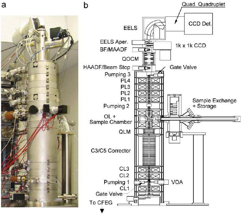 |
【*】 Detectors: HAADF, BF, EELS
【*】 QOCM: Quadrupole/octupole module called quadrupole–
octupole coupling module
【*】 Four round projector lenses: PL1, PL2, PL3, and PL4.
【*】 OL: Objective lens
【*】 QLM: Quadrupole lens module
【*】 C3/C5 corrector: quadrupole–octupole C3/C5 corrector
【*】 Three round condenser lenses: CL1, CL2, and CL3
【*】 CFEG: Cold field emission gun |
Figure 3653c. (a) The TEM column and (b) Schematic cross-section of the column. [6] |
[1] N. Dellby, O.L. Krivanek, P.D. Nellist, P.E. Batson, and A.R. Lupini, J. Electron Microscopy, 50 (2001)177 - 185.
[2] P.W. Hawkes and E. Kasper, Principles of Electron Optics (Academic Press, London, 1994).
[3] A.R. Lupini, Dissertation (Cambridge University, Cambridge, U.K., 2001).
[4] O. Scherzer, J. Appl. Phys. 20 (1949) 20.
[5] Zach J. and Haider M., Nucl. Instrum. Methods., Phys. Res. A 363, 316 (1995).
[6] Krivanek OL, Corbin GJ, Dellby N, Elston BF, Keyse RJ, Murfitt MF, Own CS, Szilagyi ZS, Woodruff JW. An electron microscope for the aberration-corrected era, Ultramicroscopy, 108 (2008) 179–195.
[7] H. Rose, Prospects for aberration-free electron microscopy, Ultramicroscopy 103 (2005) 1–6.
[8] N. Dellby, O.L. Krivanek, M.F. Murfitt and P.D. Nellist, Design and Testing of a Quadrupole/Octupole C3/C5 Aberration Corrector, Microsc Microanal 11(Suppl 2), 2131 (2005).
|