Chapter/Index: Introduction | A | B | C | D | E | F | G | H | I | J | K | L | M | N | O | P | Q | R | S | T | U | V | W | X | Y | Z | Appendix
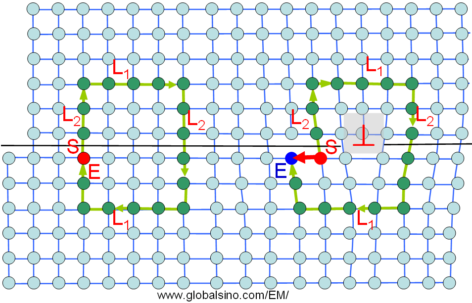
| Burgers vector b is one of the two vectors used to describe the dislocations in crystals. The Burgers vector describes the lattice displacement responsible for the discontinuity at the dislocation. The other vector of the two is sense vector ξ. The Burgers vector, named after a Dutch physicist Jan Burgers, is a vector that tells the magnitude and direction of the displacement of a part of a plane from another part which is distinguished by a line defect, called dislocation in crystalline materials. The Burgers vector is often denoted by b. The general procedure to define a Burgers vector b of a dislocation in a crystal is the Burgers circuit construction using finish-start/right-hand (FS/RH) convention. As shown in Figure 3464, in a crystalline plane perpendicular to the sense vector, the Burgers circuit in a perfect lattice can be created by a series of discrete steps from a lattice site to the next in the clockwise direction. The circuits on the left- and right-hand sides of the schematic illustration are represented by the lime arrows and the green dots. In the circuit on the left, the drawing first starts by 3 steps towards the top, then by 4 steps towards the right, then by 5 steps towards the bottom, then by 4 steps towards the left and finally, by 2 steps towards the top and thus steps back to the start site. Note that the steps at the top is the same as that at the bottom (L1 = 4 here) and the total steps on the left of each circuit is the same as that on the right too (i.e. L2 = 5 here). Both the start (S) and end (E) points (indicated by the same color, i.e. red) locate at the same lattice site in a perfect lattice. However, when a similar circuit (meaning the same L1 and L2) is drawn around a dislocation as shown in the second circuit, a closure of the Burgers circuit fails, that is the end step does not go back to the start site (indicated by different color, i.e. red and blue). The Burgers vectors are conventionally drawn from the start site to the end site. The same Burgers vectors can be obtained no matter how many steps L1 and L2 are, respectively.
Figure 3464. Burgers circuit and Burgers vector. Note that when the sense vector is reversed, the resulting Burgers vector is also reversed. Therefore, one of the characteristics of the dislocations is represented by the cross product of the sense vector and the Burgers vector, always pointing to the extra half plane of atoms that defines the edge dislocation: Furthermore, a glide dislocation is generally a line boundary between the slipped and unslipped portions of the glide (slip) plane. The line is not necessary to be straight. When it is curved some parts can be a screw dislocation and some parts an edge dislocation. For a given sense vector that points in one direction along the dislocation, the Burgers vector is invariant.
|