|
This book (Practical Electron Microscopy and Database) is a reference for TEM and SEM students, operators, engineers, technicians, managers, and researchers.
|
=================================================================================
A cubic crystal is a simple case which clearly illustrates the general construction of stereographic projection. Figure 4116a shows the stereographic projection of the six faces of a cubic structure. The cubic structure is oriented so that the xy plane lies in the horizontal plane. The solid green circles represent the planes whose normals project into the upper hemisphere, while the open red circle represents the planes whose normals project into the lower hemisphere. The normals to the four vertical faces of the cubic structure, i.e. (100), (010), (-100) and (0-10), are horizontal and thus intersect the sphere at the equator. Therefore, all the vertical planes have poles on this equatorial circle, so-called the primitive circle. The normal to the top face (001) is vertical and thus its projection lies at the center of the stereogram, and the normal to the bottom face, (00-1), projects also at the center (green open circle).
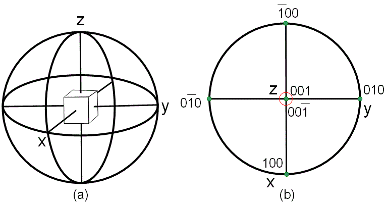
Figure 4116a. Sterographic projection of the faces of a cubic structure: (a) The cubic structure is placed at the center of a sphere, and (b) the stereogram shows the poles to the six faces of the structure.
Poles to planes are labeled as the indices with the brackets removed.
Assuming any two poles h1k1l1 and h2k2l2, then the pole to h1+h2, k1+k2, l1+l2 must lie between them along the same great circle. This is usually called the addition rule. For instance, the projection of (110) face lies between the poles 100 and 010 on the primitive circle (45° to the x and y axes) as shown in Figure 4116b. Here, h1+ h2 = 1 + 0 = 1, k1+ k2 = 0 + 1 = 1, and l1 + l2 = 0 + 0 = 0.
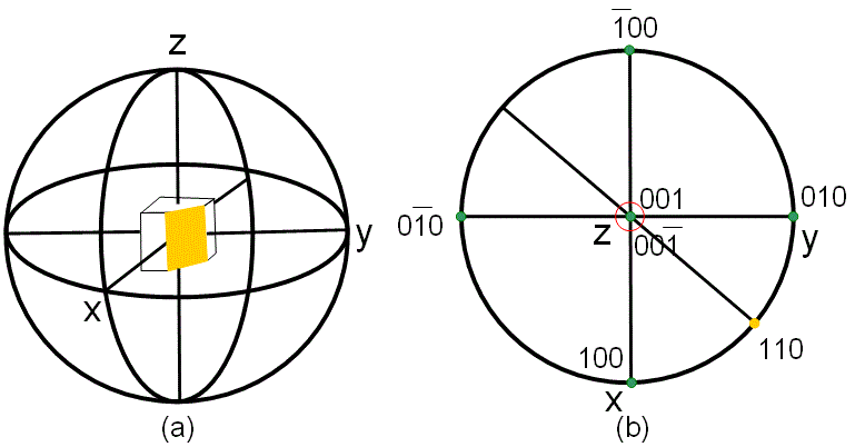
Figure 4116b. (a) The face (in green) with Miller index (110) formed by cutting off one edge of the cube, and (b) The pole (in yellow) of this face.
Figures 4116c and 4116d show stereographic projections for a cubic film with [001] and [100] normals, respectively.
![Stereographic projection for a cubic film with [001] normal](image1/4116.jpg)
Figure 4116c. Stereographic projection for a cubic film with [001] normal.
![Stereographic projection for a cubic film with [001] normal](image2/4116c.jpg)
Figure 4116d. Stereographic projection for a cubic film with [100] normal.
|