=================================================================================
The electron beam current in EMs flows between cathode and anode which accelerate the electrons emitted at the filament tip. Figure 4230a shows an example of computer-controlled SEM system. The anode is controlled by an electron-gun high-voltage power supply.
Figure 4230a. Example of computer-controlled EMs: SEM system.
As en example, Figure 4230b shows the schematic illustration of a field-emission source. the “extraction” field is generated by the first anode, which is charged by several kV of extraction voltage with respect to the tip. The second anode is then used to accelerate the electrons into the EM (electron microscope) column. The combination of two anodes operates like an electrostatic lens, producing a “virtual” gun crossover.
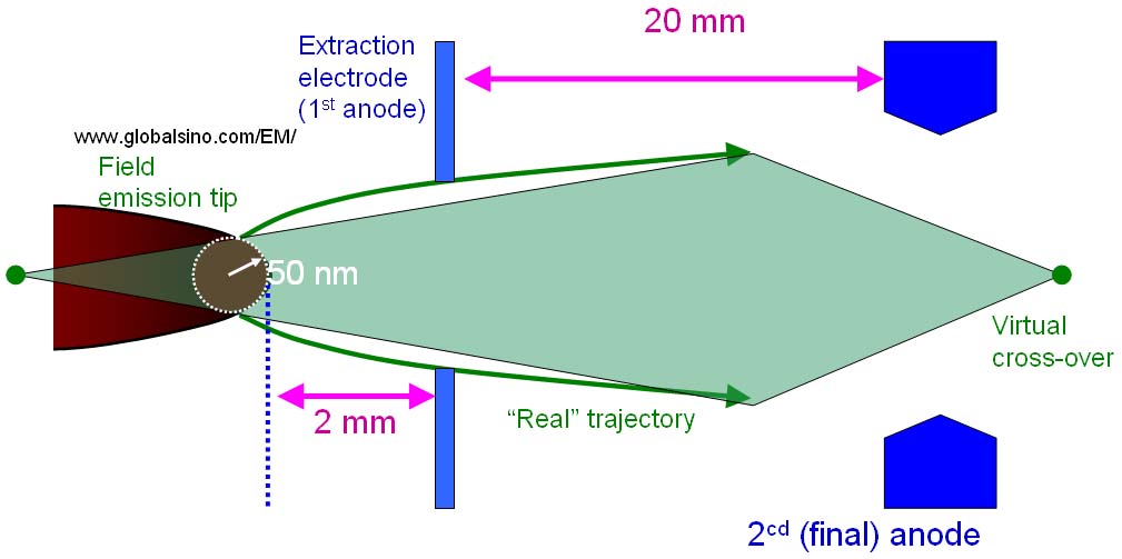
Figure 4230b. Schematic illustration of a field-emission source.
Table 4230 lists the typical operating voltages of the anodes and their applications in STEMs.
Table 4230. Typical operating voltages of the anodes and their applications in STEMs.
| |
Gun extraction voltage (anode 1, A1) |
Electrostatic gun lens voltage (anode 2, A2) |
Reference |
JEM-2100F in high-dose STEM mode |
2.8 to 3.2 kV |
6.8 to 7.3 kV |
|
EOL ARM200F at 200 kV |
3.14 kV |
7.05 kV |
[1] |
|
0.9 kV |
6.2 kV |
|
[1] Charles D. Amos, Manuel A. Roldan, Maria Varela, John B. Goodenough, and Paulo J. Ferreira, Revealing the Reconstructed Surface of Li[Mn2]O4, Nano Lett. 2016, 16, 2899−2906.
|