Chapter/Index: Introduction | A | B | C | D | E | F | G | H | I | J | K | L | M | N | O | P | Q | R | S | T | U | V | W | X | Y | Z | Appendix
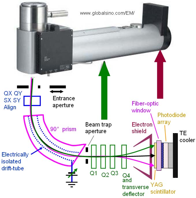
| Bias correction (sometimes called bias subtraction) removes both the detector background and the spectrometer background. Firstly, regarding the detector background, the diode capacitors in photo-diode array (PDA) detectors lose charge not only through irradiation but also as a result of their thermal leakage current, which is slightly different for each element of the array. In order to obtain values which are proportional to spectral intensity, a leakage or bias spectrum must be subtracted. This bias spectrum is recorded while electrons are excluded from the array (e.g., TEM screen lowered to block the electron beam) and will remain the same provided the integration time and array temperature do not vary. To minimize the noise content of recorded data and allow longer integration times (without total discharge by thermal leakage), the photodiode array is cooled to −20 °C by a thermoelectric device. Secondly, the spectrometer background originates mainly from backscattering of the zero-loss beam from a beam-trap aperture located in front of the detector as shown in Figure 4879 below. This background is most noticeable at high energy loss (> 1 kV) and with very thin specimens. To correct this error, this background can be recorded with no specimen in the beam [1 - 3].
Figure 4879. Top image: example of Gatan spectrometers; Bottom image: schematic of spectrometer.
[1] R. F. Egerton, Electron Energy-Loss Spectroscopy in the Electron Microscope, second edition (Plenum Press, New York, 1996).
|