Chapter/Index: Introduction | A | B | C | D | E | F | G | H | I | J | K | L | M | N | O | P | Q | R | S | T | U | V | W | X | Y | Z | Appendix
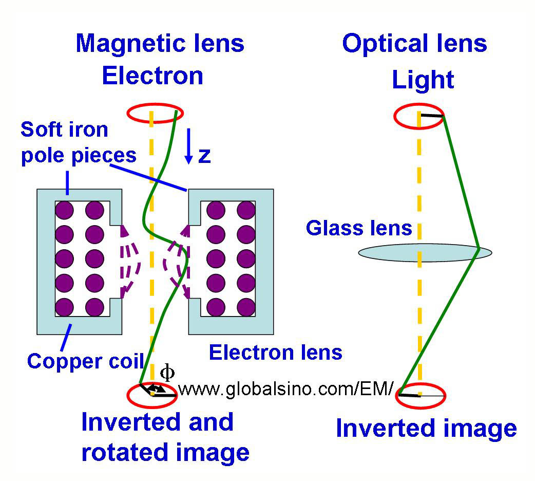
| In old TEM microscopes, the image normally rotates around the optical axis as the magnification is changed due to the Lorentz force on the electrons. However, in modern microscopes, there is an additional lens in the magnification stage, and thus this image rotation is minimized or even eliminated. In this case, the image does not rotate when the magnification is changed so that diffraction pattern is in the correct relative orientation with respect to the image. As illustrated in Figure 4903a, a current through a set of symmetrical windings around the electron-optical axis can generate strong magnetic field produced by a conventional magnetic lens. This field acts as a convex lens in electron microscopes, bringing off axis rays back to focus. The coil is enclosed by a soft iron shield (pole pieces) apart from a narrow gap between a pair of pole pieces across which the focusing field appears. The magnitude of this current in the lenses determines the strength of the lens expressed by the focal length. The image is rotated to a degree that depends on the strength of the lens. Furthermore, focal length of the lenses can be altered by changing the strength of the current. Electrons travelling initially parallel to the electron-optical axis experience a tangential force due to the interaction of the axial velocity with the radial component of the magnetic field as shown in Equation [4919c]. Therefore, the subsequent direction of moving electrons is inclined to the electron-optical axis, and the tangential velocity component interacts with the axial component of the field to produce a radial force toward the optical axis. The resulting electron paths are helical and, as the field action becomes stronger with increasing distance from the optical axis, a crossover of the electron paths in the lens focus results. An image rotation caused by the helical paths of the electrons within the focusing magnetic field is a typical feature of the action of a magnetic lens. It is also worth mentioning that EM (electron microscope) operators can observe image rotation in some cases because of adding an extra lens when changing magnification. For the people who want to have advanced study, we quantify the rotation angle below. The Lorentz force of moving electron results in a helical rotation of the electron trajectory. The rotational velocity component rθ (out of the page in direction) interacts with the z component, as shown in Figure 4903a, of the field Bz(r) to produce a force component towards the axis. By mathematical approximation, Equation [4919c] can be rewritten in a cylindrical coordinate system. The paraxial ray equation contains only the z component of the magnetic field evaluated on the optic axis Bz(z), given by, where r is the radial distance of an electron from the optic axis and Vr is the accelerating voltage. Note that the approximation has been made that the z component of the field does not depend on r. Further calculation extracts the the total image rotation, given by here, the first term (180°) stands for image inversion, and the second term stands for pure image rotation. k2 is lens parameter. The image-rotation angle is reversed when Bz or the lens current is reversed. Therefore, the image-rotation can be partially compensated by changing the sign of the currents in different lenses. The magnitude of image-rotation has to be known if directions in the image have to be correlated with corresponding directions in the specimen or in an electron-diffraction pattern. However, in some modern electron microscopes computer controls by functional softwares are added to compensate for image rotations, and thus, the operator cannot notice image rotation by changing magnification. Unfortunately, image rotation still can be seen when focusing the image.
Figure 4903a. Convex Electromagnetic Lens Figure 4903b shows the details of the helical trajectory of a single electron ray. The electrons follow the helical trajectory which converges at a fine focal point after they emerge from the lens.
Figure 4903b. Schematic illustration of electrons passing through electromagnetic lenses. For a specific microscope, if the image rotates as the magnification is changed, then we must calibrate the rotation angles as a function of magnifications.
|
 ------------------------------- [4903a]
  ----------------[4903b]