Effects of Entrance Aperture/Collection Angle on EELS and Optimization
- Practical Electron Microscopy and Database -
- An Online Book -

https://www.globalsino.com/EM/  


=================================================================================

In EELS systems, the collection angle, β, of electrons leaving the specimen is determined by the spectrometer entrance aperture and camera length.

In the case that the illumination is highly defocused (over tens of microns), the specimen is homogeneous over tens of microns, and the size of the illuminated area on the viewing screen is much larger than the spectrometer entrance aperture, the electrons that miss the spectrometer entrance aperture due to chromatic aberration will be replaced by a similar number of electrons that enter the aperture in error also due to chromatic aberration. Operating under these conditions is sometimes useful on contamination-prone specimens, or when one needs to spread the illumination over a large are to minimize radiation damage, while maintaining some spatial resolution or a high collection angle.

Table 2400a shows that by using an entrance aperture (or collection angle) that is small enough, the effect of aberrations on energy resolution of the EEL spectrometers will be minimized, although a portion of the signal is lost. Based on Table 2400b, the collection angle for EELS measurements is normally in the range of 0 – 21.5 mrad.

There is a trade-off between the EELS signal strength and energy resolution in the selection of collector aperture (also called entrance aperture) sizes, because of the following reasons:
         i) The aberrations are worse, and thus the energy resolution is degraded as the width of the electron beam entering the prism increases.
         ii) The collector aperture limits the number of electrons entering the prism more significantly, and thus the efficiency of the spectrum detection decreases as the width of the electron beam entering the prism decreases.

Aperture sizes in the range of 0.5 to 5 m are typically provided by the manufacturers and applied in various analyses.

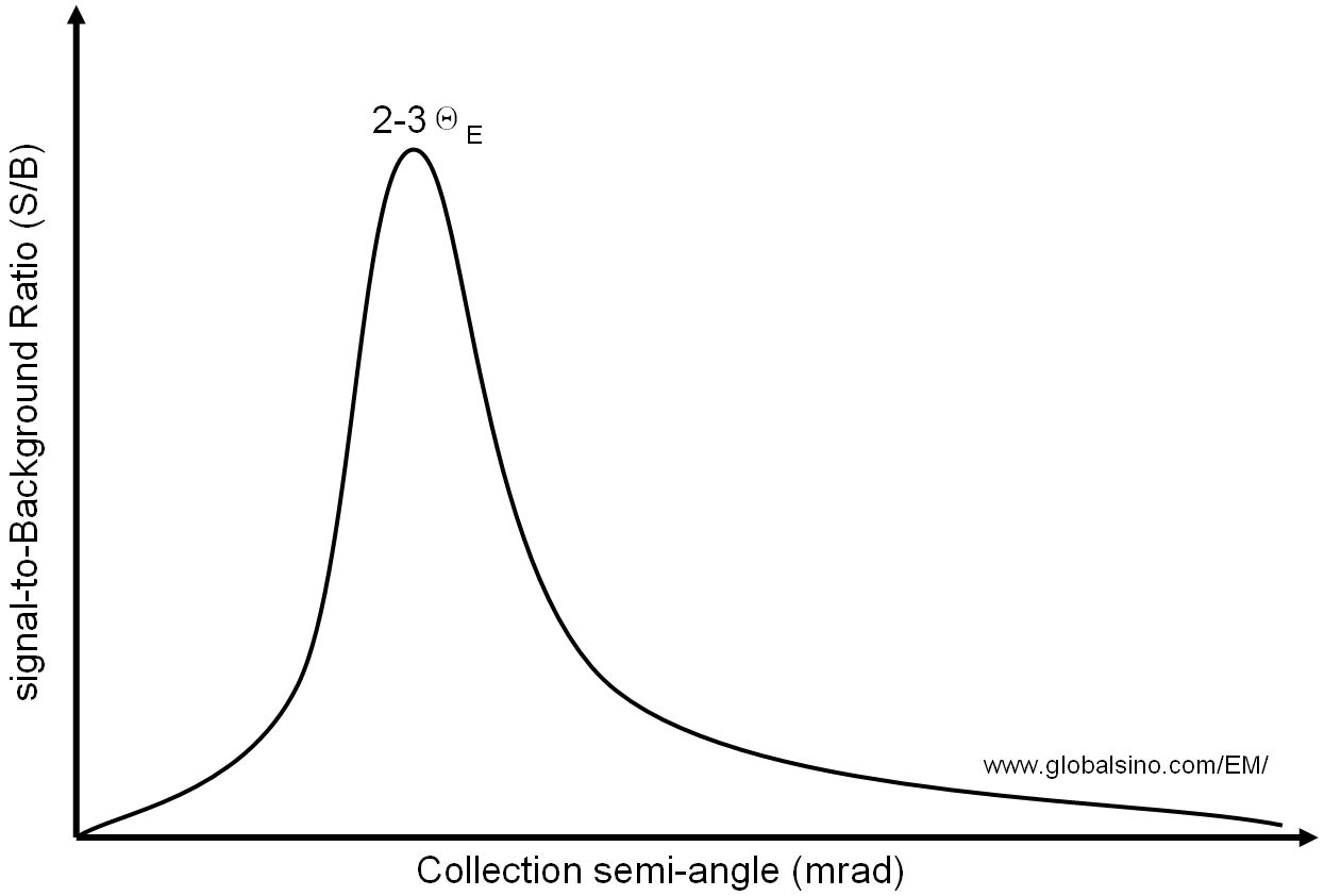
Inelastic scattering leads to a Lorentzian angular distribution with a characteristic angle approximately given by the relation for high energy electrons: [1]
         ΘE = ΔE/2E0 ------------------------------------------------ [2400]
where,
         ΔE -- The edge energy,
         E0 -- The primary beam energy (accelerating voltage of the microscope).

To optimize the sensitivity for a given edge, we need:
         i) Let the aperture size (either objective aperture in CTEM image mode, or entrance aperture and camera length in CTEM diffraction mode and in STEM mode) as large as possible in order to collect the majority of inelastically scattered electrons.
         ii) Let the collection angle as small as possible because increasing the collection angle increases both the background and the fraction of electrons that have undergone non-dipolar transitions. [1] Larger angles increase the background contribution quicker than the edge signal, resulting in a drop in the signal-to-background ratio as shown in Figure 2400a.

On the other hand, another consideration is that the magnitude of the entrance aperture is chosen as a compromise between maximizing both the signal-to-noise (SNR) and the signal-to-background ratio (SBR). In practice, a good compromise is to employ a collection angle of ~2-3ΘE. [1]

The signal-to-background (S/B) ratio of EELS as a function of the collection angle
Figure 2400a. The signal-to-background (S/B) ratio of EELS as a function of the collection angle. Optimized collection angle: ~2-3ΘE.

Table 2400a. Comparison between effects of large and small collection angles in EELS measurements.
  Large collection angles Small collection angles
   ===============================  ===============================
Intensity
High intensity Low intensity
Effect of aberrations on energy resolution is larger Effect of aberrations on energy resolution is minimized
Energy resolution
Poor energy resolution Good energy resolution
Entrance aperture in STEM/diffraction mode
A large angle is obtained with a large aperture A small angle is obtained with a small aperture and thus, limits the negative effect of the electron beam broadening by multiple scattering events in the specimen
When specimen is aligned to a zone axis 
Are normally needed due to the strong elastic scattering (diffracted beams) to high angles
Are normally proper
Signal-to-background ratio ((SBR))
See Figure 2400a
Signal-to-noise ratio (SNR)
Lower SNR Higher SNR

Table 2400b. Examples of optimized collection angles based on Equation 2400 for E0 = 30 - 400 keV.

Element Edge (eV) E (mrad)
400 keV
300 keV
200 keV
100 keV
80 keV
50 keV
30 keV
Si L3 99 0.37 0.5 0.74 1.5 1.9 3 4.95
C K 284 1.1 1.4 2.1 4.2 5.3 8.5 14.2
Ti L3 455 1.7 2.3 3.4 6.8 8.5 13.7 22.8
O K 532 2 2.7 4 8 10 16 26.6
Cr L3 575 2.2 2.9 4.3 8.6 10.8 17 29
Cu L3 931 3.5 4.7 7 14 17.5 28 47
W M5 1810 6.8 9 14 27 34 54 90.5
Au M5 2206 8.3 11 17 33 41.4 66 110
Ti K 4966 18.6 25 37 75 93 149 248

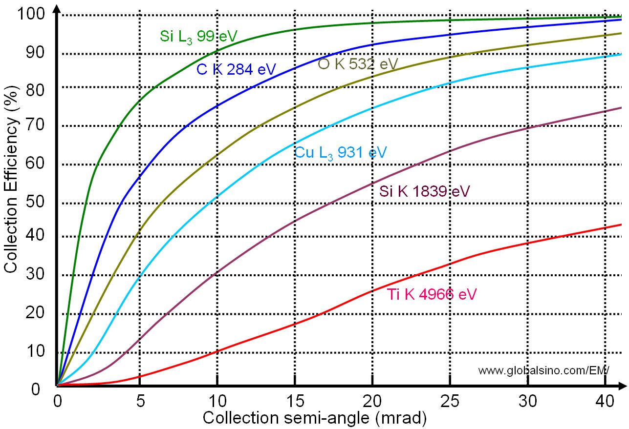
Figure 2400b shows the collection efficiency of EELS as a function of the collection angle for a primary electron beam of 200 keV. For instance, with the optimized collection semi-angle of 4.7 mrad for Cu L3 (931 eV), only ~30 % of the total available signal is collected by the EELS detector. However, as discussed above, in practice, it is not desirable to collect all of the scattered electrons.

the collection efficiency of EELS as a function of the collection angle for a primary electron beam of 200 keV

Figure 2400b. The collection efficiency of EELS as a function of the collection angle for a primary electron beam of 200 keV.


[1] C. C.Ahn, Transmission Electron Energy Loss Spectrometry in Materials Science and the EELS Atlas, 2004.


=================================================================================