Chapter/Index: Introduction | A | B | C | D | E | F | G | H | I | J | K | L | M | N | O | P | Q | R | S | T | U | V | W | X | Y | Z | Appendix
| Electron beam diameter (d)
is a major factor
in all aspects of electron microscopes, including TEM, STEM, and SEM imaging, where we use a fine focused beam. A table on the comparison of various electron sources, including their formed-probe radii, is presented in page1409. The measurement of d
is not straightforward. We can either calculate or measure it experimentally. The former is easy
but imprecise, the latter is difficult and can be equally
imprecise. Lack of universally accepted definition of the beam
diameter is one of the major problems on determination of d. The electron sources are normally narrowed down or demagnified in order to decrease the significance both of lens aberrations and of non-homogeneous electron emission over the emitting area of the source. In practice, the probe size, d, can only be reduced by using a smaller condenser aperture or by increasing the excitation of C1 lens. The microscope manufacturers give the users a list of nominal
beam sizes for each setting of the C1 lens (condenser lens 1). Unfortunately, these
values are calculated and may significantly differ from the actual
beam size. One reason is that the calculation are carried out by assuming
the electron-intensity distribution of the electron beam is
a Gaussian form, and the beam diameter is defined as the
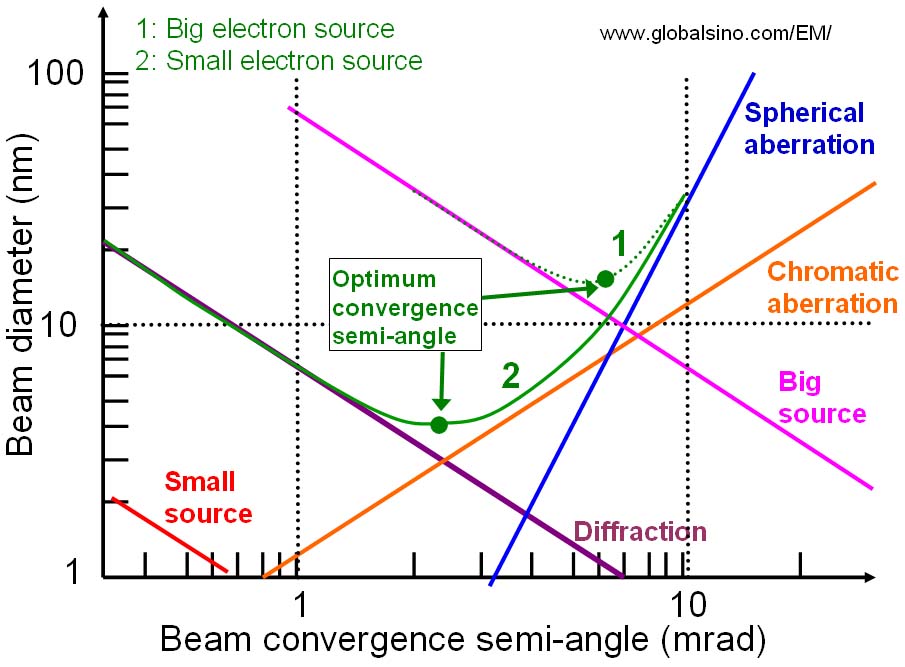
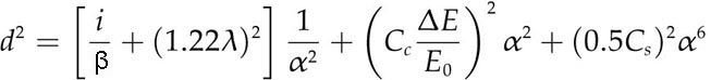
full-width at half-maximum (FWHM) of the Gaussian If no apertures are considered, the theoretical limit of the resolution of an electro-optical system is defined by diffraction of the electron (dominated by wavelength λ), and spherical and chromatic aberration of the electron lenses (mainly the objective lenses). Generally speaking, for a Gaussian beam, the beam diameter d is defined by [1]: where i is the beam current, β is the brightness of the electron source, α is the convergence semi-angle of the electron beam, Cc and Cs are the chromatic and spherical aberration coefficients of the system, and E0 and ΔE are the average energy and the energy spread of the electrons in the beam. To simplify Equation [4954a], we can make a first-order calculation of the beam size by considering ΔE = 0, so that, d = (dg2+ds2+dd2)1/2 --------------------------------------------- [4954b] where dg is the initial Gaussian diameter at the gun. ds beam broadening effect of spherical aberration in the beam-forming lens, and dd diffraction effect at the final aperture. i is the current in the electron probe and α is the aperture angle. Equation [4954c] suggests beam diameter (d) increases with beam intensity (i). Equation [4954d] indicates the diameter of the disc with minimum confusion caused by spherical aberration. Clearly, this term is not Gaussian unless the beam is correctly apertured, which, as we mentioned above, is not always possible. However, Cs correction can reduce this contribution to the beam broadening. The diameter due to diffraction (dd) is the Rayleigh criterion and refers to a spacing between two overlapping images of the beam. When the energy spread of electron beam (ΔE) is not 0, the chromatic aberration may not be ignored. So Equation 4954b becomes, d = (dg2+ds2+dc2+dd2)1/2 ------------------------------------------- [4954f] dc = Ccα(ΔE/E0) ----------------------------------------------------- [4954g] The diagram in Fig. 4954 shows how these sources contribute in a typical column according to Equation [4954b]. In systems with thermionic sources (big source), spherical aberrations tend to be the limiting factor for beam diameter, while chromatic aberrations dominate in field emission systems (small source).
Figure 4954. Diameter of the electron-beam as a function of beam-convergence semi-angle. In scanning electron microscope (SEM), spherical aberration of the probe-forming lens is increased with the increase of working distance, resulting in a larger electron-probe size. Therefore, the need to have better spatial resolution of SEM leads to shorten the working distance and consequently to change the SEM detector position. Many modern aberration-corrected STEMs have electron probes less than one atom dimension in diameter so that atom column resolution for composition analysis can be obtained. In order to improve the energy spread of the electron sources in EMs, monochromators have recently been introduced. In the best cases, the energy spread with a monochromator for any source can be reduced to < ~100 meV. There are two basic setups: the Wien filter with crossed electric and magnetic fields and the electrostatic Omega filter. It is very common that both types improve the energy width to about 0.2 eV at an acceptable beam current of several 100 pA. The single Wien filter limits the probe size to about 2 nm, whereas there is no such limitation in the case of the Omega filter. Table. 4954. Examples of probe sizes in STEM mode.
[1] J. I. Goldstein, Practical scanning electron microscopy. Electron and ion microprobe analysis, 1975.
|
 ------------ [4954a]
 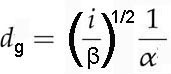 -------------------------------------- [4954c]
  ----------------------------------------------- [4954e]