|
This book (Practical Electron Microscopy and Database) is a reference for TEM and SEM students, operators, engineers, technicians, managers, and researchers. How to Cite This Book
|
=================================================================================
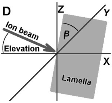
To avoid curtain effect, the TEM grid on which the lamella is can be mounted in the grid-holder of the FIB system using angles of about 45° as shown in Figure 4499. This method can be combined with the degrees of freedom of the FIB sample stage, which allows reaching the angles necessary for the different milling and cleaning processes. The milling angle with respect to the lamella surface is equal to about the azimuth angle (90°-β) as shown in Figure 4499 (D). Furthermore, mounting the grids using different rotations at angles, before and after welding the TEM lamella to it can be applied for top cleaned, top-angle cleaned, side cleaned, and bottom angle cleaned specimens.


Figure 4499. Configuration of the TEM grid with respect to the grid-holder of FIB system: (A) non-rotated way; (B) and (C) rotated in different ways; (D) the lamella is drawn in the plane XYand the ion beam on the plane XZ.
[1]
[1] Evaluation of Top, Angle, and Side Cleaned FIB Samples for TEM Analysis, Eduardo Montoya, Sara Bals, Marta D. Rossell, Dominique Schryvers, and Gustaaf Van Tendeloo, Microscopy Research and Technique 70:1060–1071 (2007).
|

