=================================================================================
Similar to Ce2Zr2O7-8, the properties of the oxides such as CeF3 and Ce3+-doped oxides (Y3Al5O12 garnet (YAG)) are closely related to the configurations of Ce4f-based states. On the other hand, the photoemission related to Ce5d-based states is due to electron transition from the lowest excited Ce3+ 5d level to the ground 4f level. [4]
Figure 2318a shows an EEL spectrum recorded in spot mode inside a catalytic particle, presenting Rh-M3, O-K, and Ce-M4,M5 white lines (see M4,5 edges).
Figure 2318a. EEL spectrum presenting Rh-M3, O-K, and Ce-M4,M5 white lines. [1]
In general, EELS spectra of cerium in materials display two sharp and strong features at 883 and 901 eV corresponding to the cerium M5 edge and M4 edge, respectively. Figure 2318b (a) and (b) shows EELS of ceria taken at two different locations of 3D (three-dimensional) ridge-valley structure of a Pt-ceria catalyst. The characteristic peak height inversion and edge splitting present normally oxidation state [2], indicating that a tall M4 edge is due to +4 valence and a tall M5 edge signals the presence of significant +3 valence. Therefore, the M4/M5 EELS ratio provides a good indication for both reduction potential and valence state. As an example, in Figure 2318b (c) the EELS M4/M5 ratio extracted from a line scan across the 3D catalyst indicates the variation of Ce valence across the material and the degree of Ce oxidation.
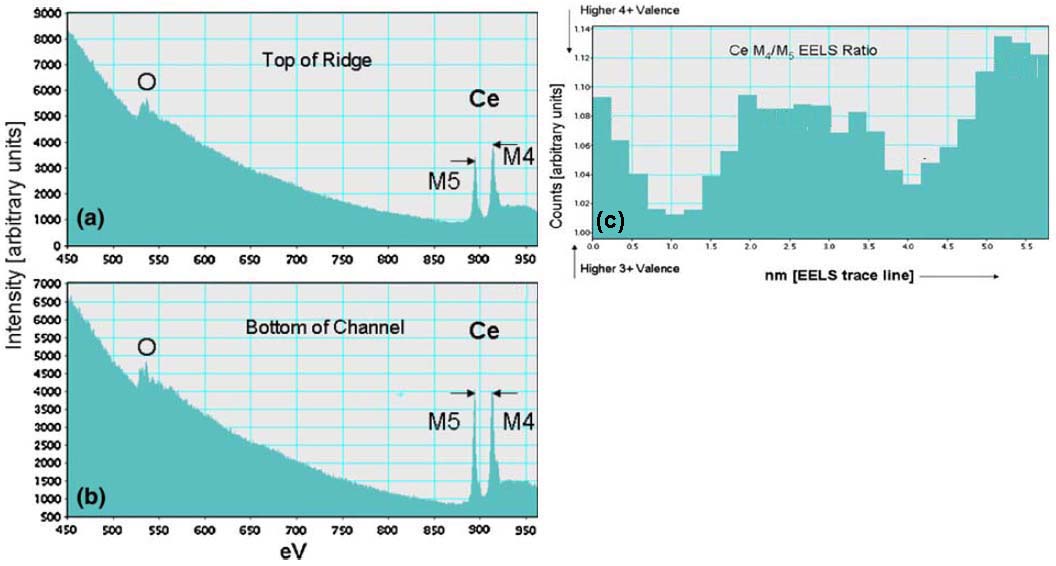
Figure 2318b. (a) and (b) EELS of ceria taken at two different locations of 3D (three-dimensional) ridge-valley structure of a Pt-ceria catalyst, and (b) EELS M4/M5 ratio extracted from a line scan across the 3D catalyst.
Adapted from [3]
Figure 2318c shows the Ce M4,5 edges of Ce4+ and Ce3+-bearing materials. The shapes and intensities of the peaks are slightly different from material to material.
Figure 2318c. The Ce M4,5 edges of Ce4+ and Ce3+-bearing materials. Monazite: CePO4, loparite: (Ce, Na, Ca)2(Ti, Nb)2O6, and cerianite:CeO2.
[6]
EELS measurement on Ce2O3 was unsuccessful because of the rapid oxidation of the sample during its transfer into the TEM system. [5]
The electron beam damage induces the changes in the spectral shape of a CeO2 specimen in thickness of 0.17λ within a few seconds. λ is inelastic mean free path. Figure 2318d shows the damage sequence from fresh CeO2 (A) to damaged CeO2 (H) with such thickness. After H, the edge showed no further changes with increase of electron dose. The M5 and M4 maxima and the peaks Y and Y' are associated with Ce4+. The electron-beam damaged CeO2 presents Ce M4,5 and O K-edge shapes that are consistent with reduction to a Ce3+ oxide. During the beam-damage process the spectrum of CeO2 changes as below:
i) Decreases in energies of the M5 and M4 maxima,
ii) Changes in shape of the near-edge structure,
iii) Inversion of the M5 to M4 branching ratio,
iv) Increase in the M5 to M4 area ratio.
Figure 2318d. The damage sequence from fresh CeO2 (A) to damaged CeO2 (H) in thickness of 0.17λ. The estimated doses in each case are (A) 3 x 10⁵ e/Å2; (B) 6 x 10⁵ e/Å2; (C) 2 x 10⁶ e/Å2; (D) 3 x 10⁶ e/Å2; (E) 7 x 10⁶ e/Å2; (F) 1 x 10⁷ e/Å2; (G) 2 x 10⁷ e/Å2; and (H) 5 x 10⁷ e/Å2.
[6]
In the analysis of valence states based on white-lines in EELS, the accuracy of the determination of the ratios of the two valence states (e.g. Ce4+/Ce3+ for cerium) depends on the ability to separate the contributions of the two oxidation states. Table 2318 lists the M5 to M4 area and branching ratios of Ce-bearing materials and Figure 2318e shows the simulated peaks originated from Ce4+ and Ce3+ valence states.
Table 2318. The M5 to M4 area and branching ratios of Ce-bearing materials. [6]
aM5/M4 branching ratio is defined as the intensity ratio I
(M5)/[I
(M4) + I
(M5)].
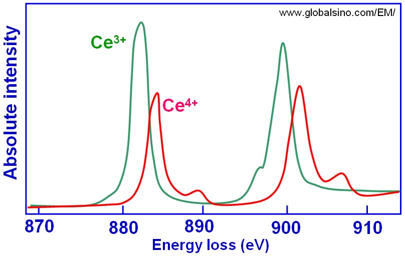
Figure 2318e. The simulated peaks originated from Ce4+ and Ce3+ valence states.
Figure 2318f shows EEL spectra of NiO and CeO2 materials. The difference of energy loss peaks between Ni L3 peak and Ce M5 is ~31 eV.
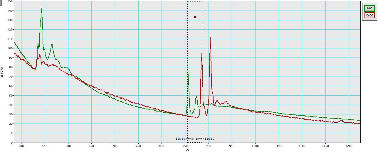
Figure 2318f. EEL spectra of NiO and CeO2 materials.
[1] S. Bernal, G. Blanco, J.J. Calvino, C. López-Cartes, J.A. Pérez-Omil, J.M. Gatica, O. Stephan a and C. Colliex, Electron microscopy (HREM, EELS) study of the reoxidation conditions for recovery of NM/CeO2 (NM: Rh, Pt) catalysts from decoration or alloying phenomena, Catalysis Letters Vol. 76, No. 3–4, 2001.
[2] Wu L, Wiesmann HJ, Moodenbaugh AR, Klie RF, Zhu Y, Welch
DO, Suenaga M (2004) Phys Rev B Condens Matter Mater Phys 69(12):125415/1
[3] Uschi M. Graham, Rajesh A. Khatri, Alan Dozier, Gary Jacobs, and Burtron H. Davis, 3D Ridge-Valley Structure of a Pt-Ceria Catalyst: HRTEM and EELS Spectrum Imaging, Catal Lett (2009) 132:335–341.
[4] E. Auffray et al.: Nucl. Instrum. Methods Phys. Res. A 383 (1996) 367–390.
[5] Ikuo Nishida, Kazuyoshi Tatsumi and Shunsuke Muto, Local Electronic and Atomic Structure of Ce3+-Containing Fluoride/Oxide Determined by TEM-EELS and First-Principles Calculations, Materials Transactions, Vol. 50, No. 5 (2009) 952 - 958.
[6] L.A.J. Garvie and P.R. Buseck, Determination of Ce4+/Ce3+ in electron-beam-damaged CeO2 by electron energy-loss spectroscopy, Journal of Physics and Chemistry of Solids 60 (1999) 1943–1947.
|
