Chapter/Index: Introduction | A | B | C | D | E | F | G | H | I | J | K | L | M | N | O | P | Q | R | S | T | U | V | W | X | Y | Z | Appendix
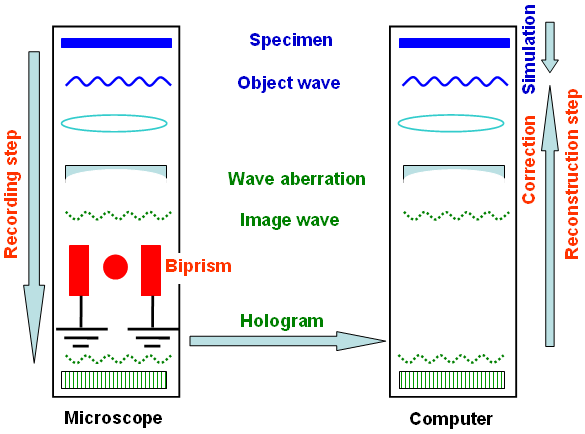
| Unlike other more direct forms of imaging, holography
(using electromagnetic, electron, or other kinds of
radiation) is a two-step process (shown in Figure 2560a):
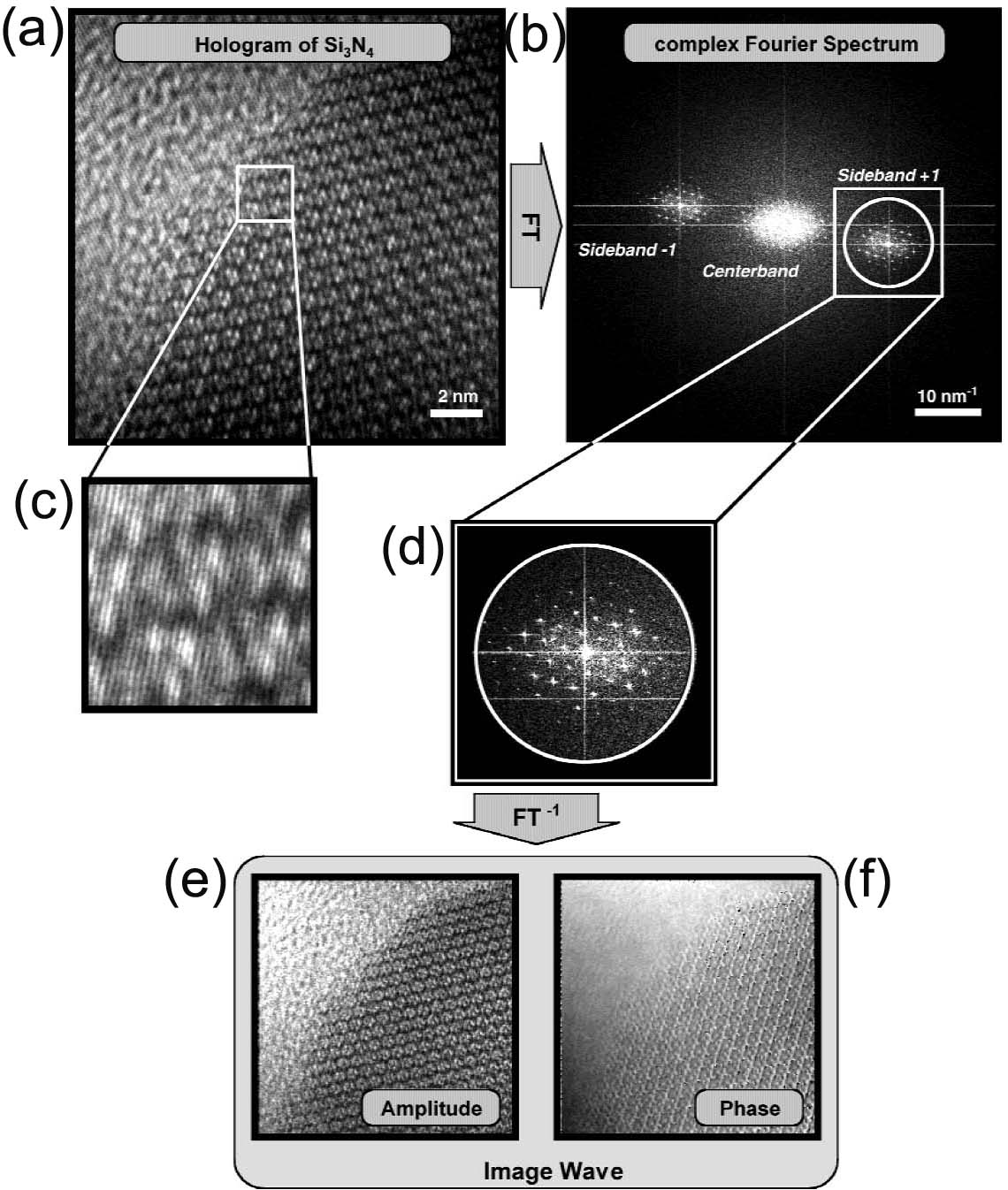
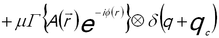
Figure 2560a. Schematic illustration of the two-step holography procedure. In the second step of electron holography analysis, the electron hologram (Figure 2560b (a)) recorded in TEM is reconstructed with the proper laws of wave optics on a personal computer (PC) [2,3]. The reconstruction process starts with the Fourier transformation of the hologram, producing a centerband and two sidebands that represent the Fourier transform of the complete image wave and its complex conjugate, respectively. [4] Both sidebands are identical except for the sign of the image phase. In this way, the amplitude and phase information of the electron exit wave are extracted from the recorded electron holograms by using digital Fourier transform as well as side band filtering [4]. The Fourier transformation of the hologram Ihol gives the complex spectrum (Figure 2560b (b)) by, [4] The first term on the right of Equation 2560a is called "centerband", representing the diffractogram of a conventional electron micrograph. The second and third terms correspond to the complex diffraction pattern and their complex conjugate and are "sideband + 1" and "sideband - 1", respectively. The sideband + 1 is cut out and centered to the origin in Fourier space as shown in Figure 2560b (d). The inverse Fourier transformation produces the reconstructed image wave, containing both amplitude (A(r)) (shown in Figure 2560b (e)) and phase (ϕ(r)) (shown in Figure 2560b (f)) information,
Figure 2560b. Image wave reconstruction demonstrated at a hologram Unlike the negligible distortions in most CTEM analyses, distortions extremely affect off-axis electron holograms as the phase information is encoded in the bending of the interference fringes [3-5]. The origin of the distortions in off-axis electron holograms are projector lenses, local variations in TEM specimen thickness, charging of the biprism filament, and shear distortion of the fiber optic of the CCD camera. [4] The distortion-induced phase modulation can normally be automatically corrected within the reconstruction process by using a reference hologram, taken by removing the specimen from the field of view using the goniometer of the microscope and without changing the optical parameters. In other words, this process compensates the geometric distortions caused by the imaging and recording system. The reference phase is subtracted from the image phase in order to correct the distortion-induced phase modulations. Furthermore, the aberrations of the reconstructured image wave can more accurately be corrected by multiplying the complex diffraction pattern of the reconstructed image wave brec(r) by the factor of the wave aberration function.
[1] Y Y Wang, M. Kawasaki, J. Bruley, M. Gribelyuk, A. Domenicucci, and
J. Gaudiello, Off-axis electron holography with a dual-lens
imaging system and its usefulness in 2-D potential mapping of semiconductor
devices. Ultramicroscopy 101: 63–72 (2004).
|

 ------------------------ [2560a]
 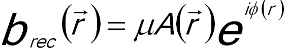 ------------------------ [2560b]