Chapter/Index: Introduction | A | B | C | D | E | F | G | H | I | J | K | L | M | N | O | P | Q | R | S | T | U | V | W | X | Y | Z | Appendix
| Turbomolecular and oil-diffusion pumps in high vacuum systems, especially TEMs, cannot work directly against atmospheric pressure and need a mechanical pre-vacuum pump in order to function as shown in Figure 4462a. In these systems, the primary vacuum pumps, e.g. mechanical (rotary) pump, are used to move large volumes of gas and can reach a vacuum from atmospheric pressure to > 0.1 Pa. Therefore, mechanical pumps are called low-vacuum/high-volume pumps, and are sometimes referred to as a pre-vacuum pump (PVP). In other words, the mechanical vacuum pumps are responsible for maintaining sufficient backing vacuum for the high-vacuum as well as for exhausting any pumped air into the atmosphere. The exhaust line from the mechanical pump must be trapped to vent to the outside and/or fit with oil mist traps in order to prevent releasing oil vapor into the EM room because these pumps continually expel small amounts of oil vapor.
Figure 4462a. Schematic illustration of pumping system in TEMs. The schematic diagram in Figure 4462b shows the vacuum system in a typical SEM. One of the main components in rotary pumps is the motor-driven rotor, in which are housed two spring-loaded scraper blades, as shown in the schematic diagram in Figure 4462c. The edges of the blades are normally faced with TeflonTM. The rotor spins via a direct-coupled AC (alternating current) motor usually at ~500 rotations per second (rps). The rotating rotor compresses the gas, from the EM, into a small volume, resulting in an increase of the gas pressure in the oil reservoir. At any given time, one side of the eccentric chamber is connected to the evacuating chamber, while the other side where the gas is being exhausted has a small flapper valve, which is opened by the pressure of the gas. The pressure of the compressed gas is high enough so that it can be expelled to the atmosphere by the unidirectional valve. A single-stage rotary pump has only one rotor and can reach a vacuum of ~10−3 Torr, while a two-stage pump with two rotors in series can reach ~10−4 Torr. A single-stage rotary pump pumps ~500 l/s of gas from a chamber. The efficiency of the vacuum pump decreases rapidly if the pressure of the chamber increases. To avoid the long pump-down-times, diffusion pumps are used to increase the pumping rate for pressures lower than 1 × 10⁻² Torr.
Figure 4462b. Schematic diagram of the vacuum system in a typical SEM. Figure 4462c shows a mechanical pump, consisting of a belt-driven, eccentrically mounted mechanism, an inlet port (valve), and an outlet port (valve). The eccentric motion of the rotator creates a vacuum that sucks air into the inlet port from the EM chamber and forces the air through the outlet port to the atmosphere. The air expands significantly in volume before sealed off by the opposite vane (Figure 4462c (b)) because the rotation axis is offset from the axis of the cylinder.
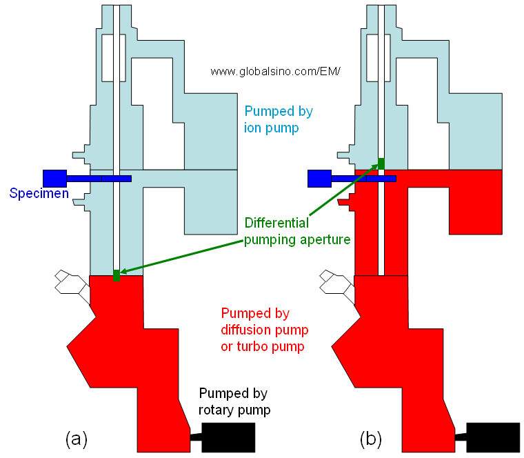
Figure 4462c. Schematic diagram showing the main components and the vacuum mechanism of rotary pumps: (a) – (d) represent different steps in a single vacuum cycle and the colors represent the movement of the parts of the air. In order to reduce friction and wear of the sliding surfaces, the chamber walls are lubricated by oil, forming an airtight seal. These pumps use normally a hydrocarbon oil as a medium, but they may have more complex synthetic lubricants with silicone, chlorofluorocarbons or fluorocarbons. For rotary pumps, it is important that proper oil levels are maintained and the oil is changed at proper intervals. As shown in Figure 4462d (a), in most modern TEMs, the electron gun, top lenses, and specimen chamber are maintained at ultra-high vacuum by an ion pump, while the viewing screens and photographic chamber are maintained at a lower vacuum, which is referred to as high vacuum, by either a diffusion pump or a turbomolecular pump. This vacuum level is backed by a mechanical (rotary) pump. Actually, in a typical TEM system, rotary or scroll pump are used to evacuate the compressed air molecules from the exhaust port of the turbo-molecular pump. However, some TEMs have lower vacuum in the specimen chamber as shown in Figure 4462d (b).
Figure 4462d. Vacuum in TEMs: (a) Modern TEMs, and (b) Some TEMs.
Mechanical pumps are noisy and dirty, but reliable and relatively inexpensive. Such pumps are normally placed outside the EM rooms due to their noise and vibration, and connected to the other pumps, attached on EM column, through a line. In general, the vacuum systems of standard EMs are composed of mechanical pump(s) (rotary pumps, rough pumps, or forepumps), diffusion pump(s), vacuum gauges, switching valves, and a network of connecting pipes. Pirani gauge is employed to measure pressure at low vacuum, e.g. those obtained by rotary pumps, based on thermal conductivity.
|