Chapter/Index: Introduction | A | B | C | D | E | F | G | H | I | J | K | L | M | N | O | P | Q | R | S | T | U | V | W | X | Y | Z | Appendix
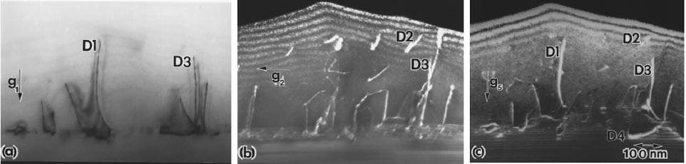
| The determination of the Burgers vectors (b) of dislocations is not a straightforward operation. The common method is that in conventional electron diffraction contrast TEM imaging, the Burgers vector is extracted by the images obtained under two-beam diffraction conditions. The Burgers vector of a perfect dislocation is represented by a full lattice translation vector in the close packed direction and on the close packed plane of the crystal, resulting in an integer value of g·b. Regardless of whether the dislocations are of edge- or screw-type, based on the invisibility criterion, the dislocations are invisible at g·b = 0 or exhibit a so-called "residual" contrast for edge dislocations when the dislocations are out of contrast [1], the dislocations are visible in the other cases. Figure 3463a shows three two-beam TEM images taken from the same area of a GaN thin film grown by MOCVD on N-face of a GaN bulk single crystal substrate. The images present three types (D1, D2, and D3) of dislocations. The conventional diffraction contrast analysis suggested that the dislocations have the Burgers vectors listed in Table 3463.
Figure 3463a. TEM images taken from the cross-section of a GaN homoepitaxial film showing a variety of dislocations: (a) Bright field with g1 = [0002]; (b) Dark-field image with g4 = [01-10]; and (c) Dark-field image with g5 = [1-102]. Adapted from [6] Table 3463. Standard g·b analysis obtained by observing the dislocation image strength in dark-field and bright-field images in Figure 3463a. Based on the invisibility criterion, a specific dislocation may or may not display in a image. For instance, the two-beam bright-field TEM image in Figure 3463a (a) can not show D2 because g1·b = 0 as indicated in Table 3463. Table 3463. Standard g·b analysis. Here,
s stands for strong contrast, w for
Even though the invisibility criterion described above gives the direction of b, its magnitude and sign is still a question. To draw an unambiguous conclusion, in many cases a combination of different techniques is applied in the Burgers vector investigations. For instance, LACBED (large angle convergent beam electron diffraction) can provide more information on the properties of Burgers vectors. It had been suggested that when a LACBED Bragg line intersects a dislocation, displacement and splitting of the Bragg line may occur [2], from which the sign and magnitude of b can be obtained. [3 - 5] This method is called Cherns–Preston rules. These rules give the magnitude of b by g·b = m+1, where m is the number of subsidiary maxima in between the main peaks obtained in a dark-field image. For instance, Figure 3463b shows the dark-field contour of D1, taken by g = [0006], has m = 5 corresponding to g·b = 6. After applying the rules for the sign of b, [7] the Burgers vector is given by b = - c = [000-1] as listed in Table 3463. Note that the intensity and position of the subsidiary fringes vary with the dislocation character and depth in the TEM sample.
Figure 3463b. (a) Bright field image and (b) Dark-field LACBED pattern (g = [0006]) A practical determination procedure of Burgers vector b of a dislocation is given below:
[1] Hirsch, P., Howie, A, Nicholson, R.B., Pashley, D.W. and Whelan, M.J., 1977,
Electron Microscopy of Thin Crystals, Krieger, New York, p. 181.
|
||||||||||||||||||||||||||||||||||||||||||||||||||||||||