Chapter/Index: Introduction | A | B | C | D | E | F | G | H | I | J | K | L | M | N | O | P | Q | R | S | T | U | V | W | X | Y | Z | Appendix
|
In general, a low voltage STEM is a hybrid instrument with the features of SEM and TEM with a convergent probe, while a high voltage TEM is a hybrid instrument with the features of TEM with both a parallel beam (for TEM function) and a convergent probe (for STEM function). Table 4113a. Comparison between CTEM and STEM.
Figure 4113a illustrates the comparison of the main contrasts in both CTEM and STEM modes.
Figure 4113a. Comparison of the main contrasts in both CTEM and STEM modes.
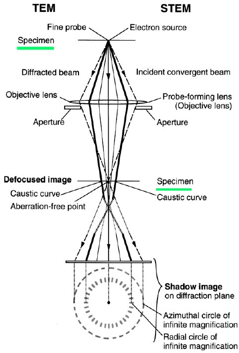
Figure 4113b shows the optical schematics of defocused TEM and STEM. The aberrations in STEM mode can be detected and corrected using the symmetry in the Ronchigram that includes the azimuthal and the radial circles of infinite magnification [1]. The solid lines represent the electron scattering direction at the radial circle in STEM mode, corresponding to the caustic curve in TEM mode. The azimuthal circle (broken line) is related to the angle of focusing on the specimen, i.e. part of the highly scattered electrons, which cross the optical axis on the specimen.
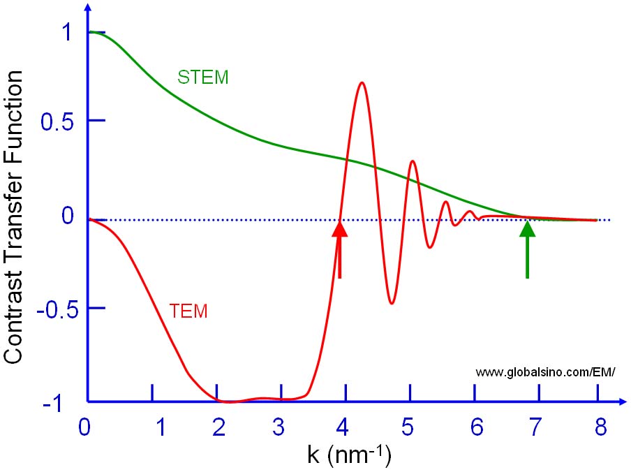
Figure 4113b. The optical schematics of defocused TEM and STEM. Adapted from [3] Figure 4113c shows the schematic comparison between contrast transfer functions (CTFs) for a parallel-beam CTEM and a STEM. For TEM imaging, the higher frequencies should be excluded by a proper objective aperture marked by the red arrow because they introduce contrast reversals. For STEM imaging, a proper probe-forming aperture should be applied to match the need of the spatial frequency marked by the green arrow.
Figure 4113c. Schematic illustration of contrast transfer function (CTF) for: (a) A parallel-beam CTEM and (b) A STEM.
It can be considered that the coma-free alignment in TEM mode corresponds to STEM alignment with Ronchigram in STEM mode, that is the Ronchigram can be used to detect coma aberration in a probe-forming lens (the objective lens in STEM) [2]. Therefore, the STEM coma-free alignment is carried out by coinciding the aperture center with the center of the azimuthal- or radial-circle. Note that the Ronchigram locates on the diffraction plane. Table 4113b. Equivalent functions in TEM and STEM modes.
[1] N. Dellby, O.L. Krivanek, P.D. Nellist, P.E. Batson, A.R. Lupini, J. Electron Microsc. 50 (2001) 177.
|