Chapter/Index: Introduction | A | B | C | D | E | F | G | H | I | J | K | L | M | N | O | P | Q | R | S | T | U | V | W | X | Y | Z | Appendix
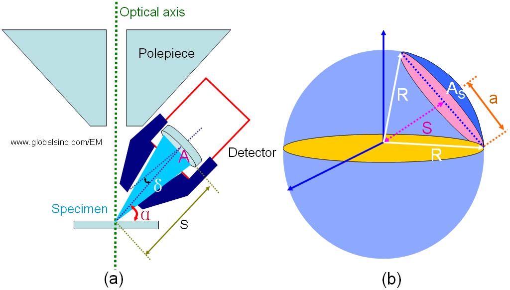
| For X-ray measurements, e.g. EDS, two main factors that affect the number of X-ray photons which reach the detector are: Characteristic X-rays are generated isotropically in the thin sample. Only those emitted in the small solid angle (also called collection angle) "seen" by the EDS detector are eligible for detection, provided they are not absorbed in the sample on their way out. In other words, the solid angle of EDS detector (Ω) is an important factor in determining the quality of EDS analysis. This angle is the angle that faces at the analyzing point on the specimen by the active area of the detector front face. The solid angle can be given by, where, More accurate calculation can be done by replacing A by AS, and S by R. AS is the equivalent surface area of a sphere nominally located at the same radial distance from the specimen [1], as shown in Figure 4631a (b). Based on Zaluzec's theory [2] and Equation 4631a, for a detector whose active area is circular in cross-section, or whose active area is defined by a circular collimator, the solid angle is calculated by,
Figure 4631a. (a) Schematic showing the positions of the EDS detector and specimen, and (b) The geometry for solid angle calculation. As shown in Figure 4631b, the desired collection angle (Ω1) is set by the collimator (when δ = 0, Ω is maximized) placed in front of the detector crystal. Note that the detector crystal is used to prevent unwanted or spurious X-rays from entering the detector. An typical example of collection angle of EDS detectors is 0.3 steradians (sr). In modern EMs, Windowless in-column silicon drift detectors have been installed, which provides very high collection angle (e.g. 0.9 sr) and thus, allows high detection efficiency (e.g. 7% of the x-rays emitted from the EM specimen).
Figure 4631b. Schematic illustration of the desired collection angle in an EDS detector system. Furthermore, you need to keep in mind that the solid angles are often incorrectly calculated and mostly overestimated by the manufactures because they get those numbers based on the optimized column design on their microscope(s). To have highly accurate evaluation on a specific microscope, the microscope owners need to do their own examinations. Fortunately, in many cases, the solid angle can be optimized and thus maximized in order to achieve high geometrical collection efficiencies. For instance, a range of alternate geometries for silicon drift detectors can be used in the columns of conventional electron microscopes because of the compact size of the detectors. Under certain electron-optical operating conditions, the detected intensity (I) of a specific x-ray line is given by, Idetected = κ · Ω ----------------------- [4631c] where, The count of X-ray acquisition can be increased mainly by: For the TEM configuration with a top-entry type EDS detector, the detector is placed above the objective lens in a TEM system with a high viewing angle (e.g. 70 °) to a horizontal specimen. Since X-rays entering the detector take a large take-off angle (TOA) against the specimen, a high accuracy of quantitative analysis can be obtained. However, with such configuration, the solid angle of the detector against the specimen is small, resulting in low detection efficiency.
[1] Nestor J. Zaluzec, Calculating the Detector Solid Angle in X-ray Energy Dispersive Spectroscopy, Microsc Microanal 15(Suppl 2), 2009.
|
 ------------------------------------------------- [4631a]
  --------------------- [4631b]